


Preface
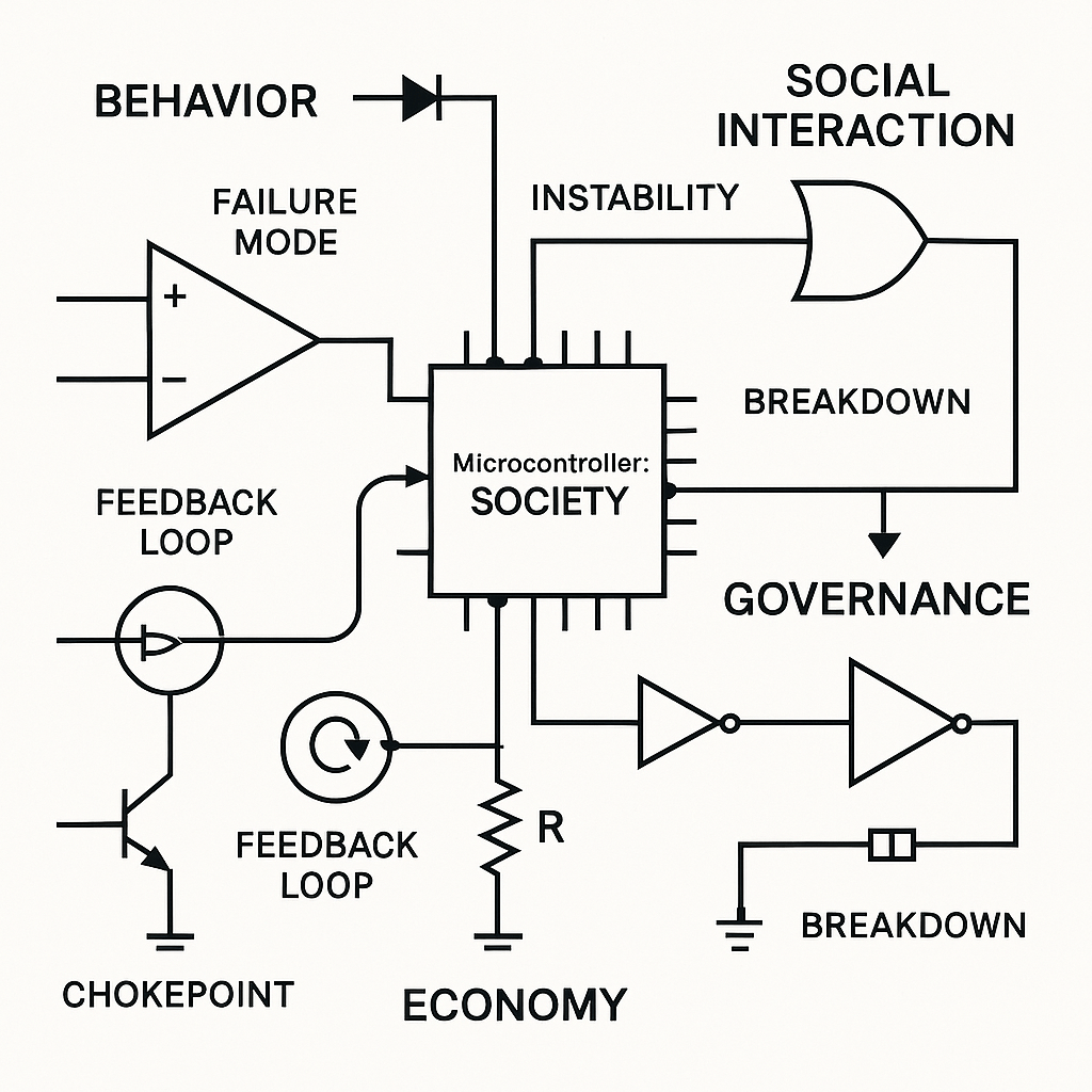
Over the past few months, I’ve created a schematic-based symbolic language that maps human behavior, social interactions, economic systems, and governance onto actual electronic circuits. Instead of words or written symbols, this language uses standard electrical components (wires, resistors, capacitors, inductors, diodes, transistors, amplifiers, oscillators, filters, feedback loops, microcontrollers, and more) to show how people and societies succeed or fail under the laws of physics (electricity) and information.
I decided to do this because of my professional background in electronics and software engineering, and as a game developer that spent years learning and emulating the world around us. It occurred to me that electronics components, and more so, electronic symbology, could mimic or even model human behavior, society, economics and governance. And so, this is my first attempt at creating a new concept, that to my knowledge does not exist anywhere.
By “wiring” these symbols together into functioning circuit diagrams, I can pinpoint exactly where a social system is efficient or where it breaks down. If a community is overloaded like a blown transistor or locked in deadlock like an unfed gate, the diagram shows the precise failure mode. From there, you can trace, debug, and redesign, just as you would with any electronic prototype, to eliminate chokepoints, restore proper feedback, and create a more responsive, stable system.
Again, to my knowledge, no one else has built a full-fledged, electronics-style language that literally translates beliefs, institutions, and economic flows into schematic diagram form. There are related fields that use metaphors, but none use real circuit symbols, one-to-one, to model human, societal and economic dynamics. While people have borrowed circuit analogies for feedback in social or economic systems, this is the first comprehensive effort to draw society-level dynamics as actual electronic schematics rather than just a metaphor.
My goal is simple: attempt to find real-world solutions to real-world problems of various human scales (though not perfect). My attempt is to identify real societal failures and offer a practical, testable method to fix them. These circuit-based models can be built at small (or large) scales, tested, and iterated until they operate correctly, just like any electronic design. In a world drowning in complex problems, this approach provides a clear, physics-grounded framework for understanding and improving how we govern ourselves and interact with one another.
Keep in mind that this is a new concept and a work-in-progress, so there will be plenty of mistakes, errors, or incomplete circuits. Over time, I intend to fully flesh this out and test all the circuitry, using various design methods.
I do hope this makes a positive impact on society, with these modular subsystems, and I invite others to participate and collaborate. We know the problems we face; it’s now a matter of identifying their causes and fixing them.
Primal Consciousness (God) has given us physical rules and laws, together with its intrinsic symbolic language, so that we can better understand ourselves, our relationship to each other, the universe and expand the human experience.
Table of Contents
Part 1: Welcome to the Circuit World
Part 2: The World as Signals – Rethinking Life Through Electricity
Part 3: Capacitors, Diodes, and Resistors – The Core Components of Human Nature
Part 4: Logic Gates and Life Decisions – Building Minds with AND, OR, and NOT
Part 5: Timing, Memory, and Delay – How Behavior Evolves Over Time
Part 6: Feedback Loops – Why We Get Stuck, Spiral, or Grow
Part 7: Burnout, Collapse, and Systemic Overload – When Circuits Overheat
Part 8: Emotions as Circuits – The Electric Self
Part 9: Relationships as Circuits – Wiring for Love, Conflict, and Repair
Part 10: Empathy, Projection, and Communication Gates – Translating Emotional Signals
Part 11: Group Dynamics and Swarm Logic – How Behavior Spreads in Crowds
Part 12: Conflict and Repair Architecture – Contradiction Gates, Apology Resets, and Peace Latches
Part 13: Rituals, Culture, and Shared Circuits – Encoding Meaning into Systems
Part 14: Economics as Electric Flow – Modeling Money, Work, Scarcity, and Value
Part 15: Wealth Distribution, Rent, and Extraction – Skimmers, Gates, and Value Loops
Part 16: Debt, Interest, and Collapse – Time-Based Inversion and Systemic Overload
Part 17: Institutions, Law, and Governance Logic – Constitutions, Override Switches, and Power Regulators
Part 18: Corruption, Collapse, and Revolt – Feedback Hijacks and System Failures
Part 19: Market Behavior and Monetary Psychology – Speculation, Inflation, and Value Loops
Part 20: Governments, Laws, and Constitutions – Logic Systems for Collective Behavior
Part 21: Ideology as Circuit Logic – Dogma, Belief Cascades, and Narrative Encoders
Part 22: Designing People – How to Build Personalities, Characters, and Agents from Circuits
Part 23: Debugging Society – How to Diagram a System’s Failure and Rewire It
Part 24: Rewiring Ourselves – A Personal Practice of Emotional Circuit Mapping
Part 25: Toolkit, Templates, and Symbol Resources – Fonts, Icons, and Circuit Libraries for Emotional Design
Part 1: Welcome to the Circuit World
“What if your feelings could be drawn like a light switch? What if your arguments, dreams, addictions, or beliefs could be laid out on a table of wires, signals, and all, so you could finally see how they work?”
This series is about a new kind of language. Not one made of words or equations, but of resistors, capacitors, amplifiers, and feedback loops. A symbolic system that lets us draw human behavior like we draw electronic systems.
This is not about replacing feelings with cold logic. Quite the opposite. It’s about finally giving our emotions, relationships, institutions, and ideologies the precision, respect, and visibility we give to our phones and satellites.
Because what we call “society,” “mind,” “trust,” or “fear”—these are not random clouds of emotion. They are systems. Circuits. Loops. Patterns. Machines made of memory, belief, and behavior.
And for the first time, we can draw them. Build them. Understand them.
The Problem: Behavior is Invisible
We feel it. We sense it. We suffer it. But we can’t see it.
Therapists try to draw diagrams. Economists use charts. Politicians give speeches. None of it quite captures how things actually flow, how decisions feed into emotions, how shame loops into addiction, how trust becomes control, how beliefs resist contradiction.
Most behavior models are vague, contradictory, or entirely metaphorical. We need a structure. A grammar. A toolkit.
Insight: Behavior Is a Circuit
Circuits aren’t just for electronics. They’re for anything that follows:
- Input → Processing → Output
- Feedback
- Memory
- Thresholds
- Timing
That’s us.
We wake up, take in a signal (a text, a feeling, a look), process it through our internal logic (beliefs, trauma, expectations), store some of it (memory), react (speech, silence, affection, defense), and sometimes we loop it. We loop it hard.
A Simple Schematic: “Obedience”
Let’s start with a familiar behavior. Say someone gives you a command. You follow it. That’s obedience.
In circuit terms:
- The command is an input voltage.
- Your internal threshold determines whether you act.
- If the command crosses your threshold, the switch closes and action occurs.
Here’s the schematic:

[Command Signal] ──▶ [Comparator Gate (V_ref = Authority Threshold)] ──▶ [Action Output]
If the command is too weak? No action.
If it’s strong and you’re wired for obedience? The current flows.
Want to make rebellion? Add a resistor or a signal inverter.
Want to model delayed obedience? Add a capacitor or a time-delay switch.
You get the idea.
Why This Matters
This isn’t just a clever metaphor. It’s a tool for design, diagnosis, and understanding.
We can now:
- Draw emotional loops that keep people stuck in shame.
- Visualize political dynamics like crowd behavior or power centralization.
- Model economies where value is siphoned unfairly.
- Build mental health maps of internal states.
- Rewrite institutions, games, and cultures using logic and feedback.
This language lets us see the invisible, not just to label it, but to fix it, tune it, even design it better.
What Comes Next
This is the beginning of a long and fascinating journey. We’ll build a complete symbolic system that lets you:
- Translate feelings into circuits
- Build characters, systems, and stories from logic
- Understand emotions, behaviors, society, economics through flow diagrams
We’ll start with the core components, emotions as diodes, trauma as clamps, trust as voltage thresholds.
And by the end, you’ll be able to design an entire personality, culture, economy, or institution as a working symbolic circuit.
Part 2: The World as Signals – Rethinking Life Through Electricity
“What if every moment of life was a signal? Every word a pulse, every emotion a charge, every decision a switch? What if your entire life could be seen as an elegant, humming circuit, alive with meaning?”
Welcome to the next step in our symbolic journey.
In the first section, we introduced the idea that human behavior is a circuit, that we can map emotions, thoughts, and institutions using the same tools we use to understand electronics. Now, we zoom in on the fundamental metaphor that powers it all:
Everything is Signal
A signal, in electronics, is a flow of energy carrying meaning. In life? It’s the same:
- A word is a signal.
- A look is a signal.
- A policy, a tone of voice, a text message, or a silence, all signals.
We constantly receive them, interpret them, respond to them, or loop them. Some we ignore. Some change our lives.
Let’s look at the basics, translated for the human world.
ELECTRICAL FUNDAMENTALS, HUMANIZED
1. Voltage = Potential / Desire / Emotion
- It’s the pressure behind a signal.
- High voltage? Intensity, urgency, power.
- Low voltage? Weak interest, flat emotion.
Example:
A gentle request might be 1.5V.
A command with urgency? 12V.
2. Current = Effort / Action / Engagement
- It’s what actually flows, what you do with the pressure.
- You can have high voltage (strong emotion) but no current (you don’t act).
Example:
You feel rage (high voltage) but suppress it. No current flows.
3. Resistance = Fear / Hesitation / Friction
- Anything that blocks flow.
- High resistance? You feel tension or delay.
- Low resistance? You act smoothly and quickly.
Example:
A person with trauma may have high emotional resistance.
Put Together: The Emotional Circuit Equation
In electronics:
Current (I) = Voltage (V) / Resistance (R)
In human terms:
Action = Emotion / Hesitation
A powerful idea. You act most when you feel strongly and aren’t afraid.
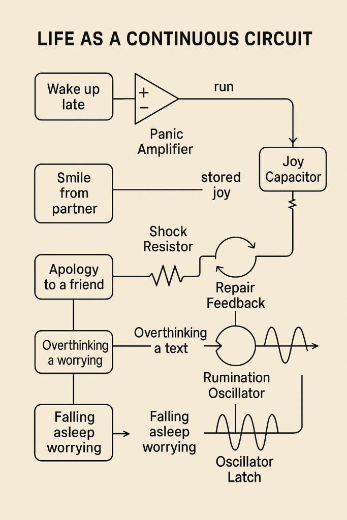
LIFE AS A CONTINUOUS CIRCUIT
Let’s walk through a day in circuits.
| Real-World Event | Circuit Behavior |
|---|---|
| Wake up late | High voltage (panic) → low resistance → immediate current (run) |
| Smile from partner | Positive signal → emotional capacitor charges (stored joy) |
| Bad news email | Negative voltage spike → current suppressed by resistor (shock) |
| Apology to a friend | Delayed feedback loop → output reversal (repair) |
| Overthinking a text | Feedback loop ↻ capacitor charging → delayed output |
| Falling asleep worrying | Oscillator circuit stuck in rumination mode |
We aren’t just people, we’re processors. We run circuits of emotion, logic, belief, memory, power, and feedback, in every moment.
A Simple Diagram: “Emotional Response Delay”
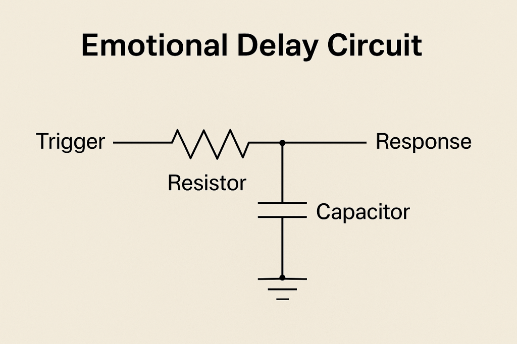
When someone says something hurtful and you don’t react right away, that’s a capacitor and resistor working together. Emotion charges up, but is released slowly.
Here’s the circuit:

[Input Signal] ──▶ [Capacitor + Resistor] ──▶ [Delayed Emotional Output]
Here’s the Emotional Response Delay schematic with standard symbols:
- Input Signal (voltage source icon)
- Series capacitor C and resistor R
- Output Signal node
Larger C and R values increase delay (greater regulation); too small and the circuit (or emotional response) “explodes.”
The more emotionally regulated someone is, the bigger the capacitor and the stronger the resistor.
Too little of either? They explode.
Systems Are Just Bigger Circuits
- A family is a feedback network.
- A company is a logic board.
- A government is a voltage regulator with hundreds of latches and overrides.
- A school is an oscillator loop for behavior.
- A culture is a layered mesh of recursive logic, feedback delay, and emotional encoding.
All of them run on signal, memory, thresholds, and feedback. Once you see the world this way, you can’t unsee it.
Where We’re Headed Next
We’ve introduced the fundamentals. But soon, we’ll move beyond metaphor:
- Building circuits for specific emotions
- Modeling behavior like actual engineers
- Designing systems with human logic
We’ll start drawing real emotional devices, circuits for trust, addiction, forgiveness, identity, and betrayal.
Part 3: Capacitors, Diodes, and Resistors – The Core Components of Human Nature
“What if memory was a capacitor? What if trust was a diode? What if fear was just resistance? Suddenly, the mind isn’t a mystery, it’s a machine you can learn to read.”
We saw how life is signal, that emotions, actions, and relationships flow like electricity through logic and resistance. We now dig deeper into the building blocks of this symbolic circuit language.
These components are not metaphors. They are working models. When we say “someone’s carrying emotional charge,” we can diagram it. When we say “they’re blocking connection,” we can build the gate that’s closing.
Let’s meet the core elements of your internal circuit board.
Capacitor = Emotional Memory
A capacitor stores energy. Slowly it charges, and slowly it discharges. Sound familiar?
That’s:
- Holding a grudge
- Bottling up emotion
- Waiting before you act
- Building trust or resentment over time
Human Behavior:
- A larger capacitor = deeper memory
- A leaky capacitor = forgets or forgives quickly
- A reverse-wired capacitor = stores emotions inappropriately (laughs during grief)
Diagram: Emotional Memory Circuit

[Input Emotion] ──▶ [Capacitor] ──▶ [Delayed Expression]
The Emotional Memory schematic uses:
- Input Emotion node driving the circuit.
- A capacitor C to ground storing the emotional charge.
- The Delayed Expression node taps the stored charge with a slow discharge path.
Larger capacitance means deeper emotional memory; leakage or reverse wiring changes forgetting or misaligned responses.
Diode = One-Way Trust or Emotion
A diode only allows current to flow in one direction. It blocks the reverse.
In people?
- You love them, but they don’t love back.
- You forgive, but they don’t.
- One-way communication. Unreciprocated effort.
Human Behavior:
- Healthy trust is a bidirectional signal.
- A diode in love is unrequited.
- A Zener diode breaks if the emotional pressure gets too high, snap!
Diagram: Unrequited Love
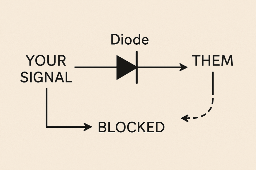
[Your Signal] ──▶ [Diode] ──▶ [Them]
[Their Signal] ──|→ BLOCKED
Here’s the Unrequited Love schematic with a diode as one-way trust:
- Your Signal feeding a standard diode
- Them node receiving the forward current
- A dashed Blocked path for Their Signal returning
This visualizes how emotion flows one way when trust or love isn’t reciprocated.
Resistor = Fear, Caution, Hesitation
A resistor slows current. It lowers flow.
You use resistance when:
- You’re cautious
- You want to wait and see
- You hesitate to express how you feel
Human Behavior:
- High resistance = fear, trauma, distrust
- Low resistance = impulsivity, vulnerability
- Resistance + heat = burnout
Diagram: Fear Filter
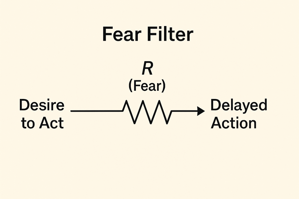
[Desire to Act] ──▶ [Resistor] ──▶ [Delayed Action]
Here’s the Fear Filter diagram with standard symbols:
- Desire to Act flowing through
- Resistor (R: Fear)
- Delayed Action
Increasing R reduces output flow, more fear, less action.
Combining Them: Emotional Regulation
Here’s how you regulate your response:
- Capacitor stores the emotion
- Resistor slows the release
- Output happens only if the charge builds up
Emotional Regulation Circuit:

[Trigger Event] ──▶ [Capacitor] ──▶ [Resistor] ──▶ [Action]
Here’s the Emotional Regulation Circuit:
- Trigger Event input arrow feeds into the capacitor (C: Emotion Storage).
- Capacitor output goes into the resistor (R: Release Delay).
- The resistor’s output arrow drives the Action node.
People with larger C and higher R respond more slowly but stay calm; smaller values lead to quick reactions or “explosions.” By adjusting C and R, you tune your response speed and intensity.
This is why some people explode quickly, while others stay calm. Their components are wired differently.
You Are a Board of Behaviors
You are made of:
- Capacitors: feelings you hold
- Resistors: habits you formed
- Diodes: directions you trust
- Logic gates: choices you make
- Oscillators: moods that loop
- Feedback loops: beliefs you reinforce
And these can all be drawn. Modeled. Studied. Remixed.
We’re not simplifying humans. We’re giving humans structure and clarity, so we can understand ourselves, and each other, better.
Part 4: Logic Gates and Life Decisions – Building Minds with AND, OR, and NOT
“Every decision you make is a logic gate. Sometimes you need two things to say yes. Sometimes one. Sometimes a no cancels everything. That’s not chaos, it’s logic circuits.”
We’ve explored how emotions flow like electricity and how core components like capacitors (memory), diodes (one-way trust), and resistors (hesitation) shape our responses. Now it’s time to move up a level.
Now, we look at decision-making as it truly is: a logic circuit.
Logic gates are the heart of electronics, and they’re also the heart of behavior. They determine whether current flows or stops, depending on conditions. In humans, these conditions are beliefs, feelings, and expectations.
What Is a Logic Gate?
A logic gate takes one or more inputs and gives a single output. The output depends on the rules of the gate.
In people? A logic gate is:
- “I’ll go out if I feel safe.”
- “I’ll forgive if I trust and I believe it was an accident.”
- “I’ll act unless someone stops me.”
Logic gates decide your behavior, every moment.
Let’s break down the major gates.
AND Gate = All Conditions Must Be True
You act only if everything lines up.
Truth Table:
| Input A | Input B | Output |
|---|---|---|
| 0 | 0 | 0 |
| 1 | 0 | 0 |
| 0 | 1 | 0 |
| 1 | 1 | 1 |
Example:
“I’ll share my secret only if I trust you AND I feel safe.”
Diagram:
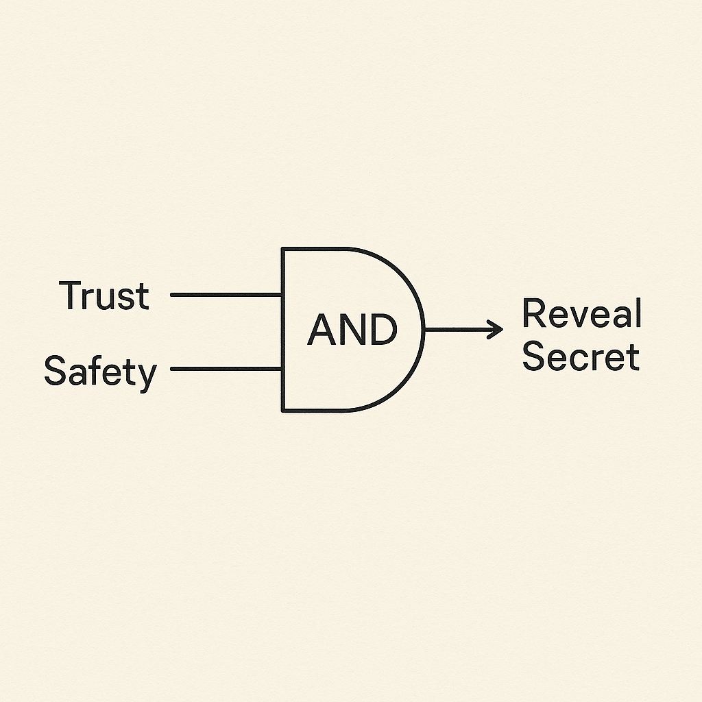
[Trust] ──▶
           AND ──▶ [Reveal Secret]
[Safety] ──▶
OR Gate = Any Condition Is Enough
You act if at least one condition is met.
Example:
“I’ll join the protest if I’m angry OR my friends are going.”
Diagram:
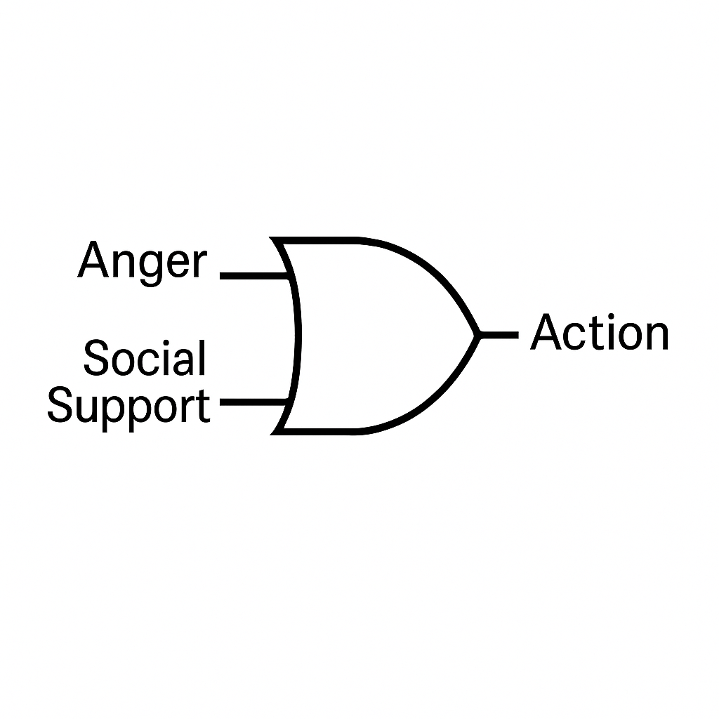
[Anger] ──▶
           OR ──▶ [Action]
[Social Support] ──▶
Here’s the OR gate schematic using standard symbols:
- Anger and Social Support feed the left side of an OR gate.
- Action emerges from the right side.
This shows that either condition alone is enough to trigger action.
NOT Gate = Inversion of Input
This flips the signal. A YES becomes a NO. In real life, this is:
- “I will not go if they’re involved.”
- “If I don’t trust you, I’ll walk away.”
Diagram:

[Trust] ──▶ NOT ──▶ [Exit]
Here’s the NOT Gate = Inversion of Input schematic using standard symbols:
- Trust enters the inverter triangle.
- The bubble inverts the signal.
- Exit is the inverted output.
It’s your internal alarm switch, the “unless” in your decisions.
Putting Them Together: Real Life Logic Circuits
Let’s model this decision:
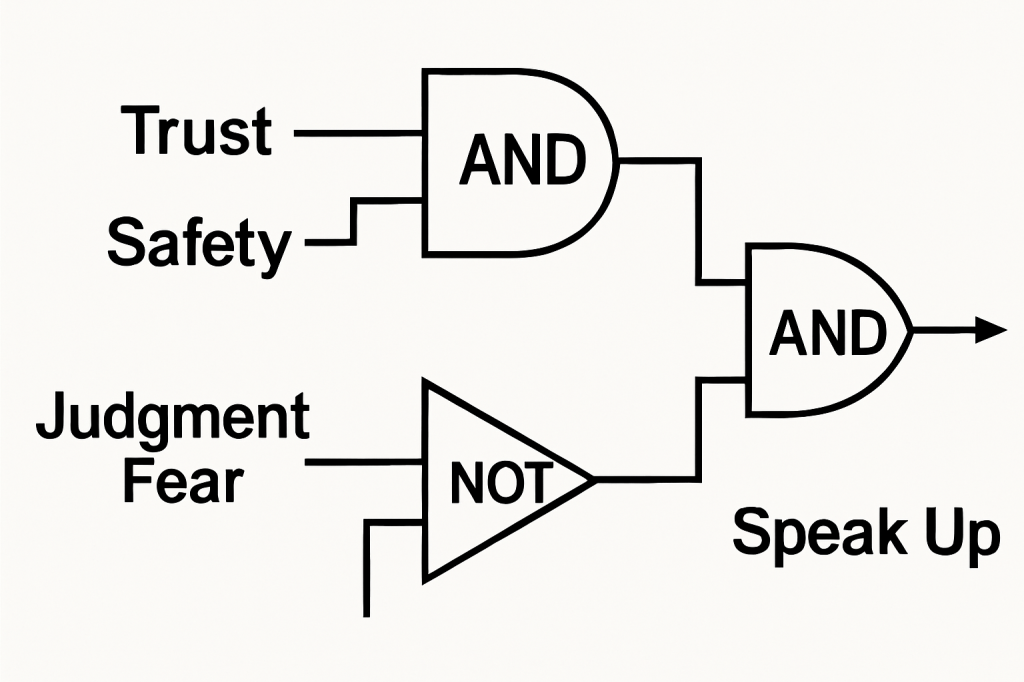
“I’ll speak up if I trust them AND I feel safe, but not if I fear being judged.”
We build it like this:
- Two inputs into an AND gate: [Trust] and [Safety]
- A third input goes into a NOT gate: [Judgment Fear]
- Final output only happens if both AND and NOT pass
Composite Circuit:
[Trust] ──▶
            AND ──▶
[Safety] ──▶        ┐
                    ├──▶ AND ──▶ [Speak Up]
[Judgment Fear] ──▶ NOT ──▶
Here’s the composite Real Life Logic Circuit:
- Trust and Safety feed the first AND gate.
- Judgment Fear feeds the NOT gate.
- Both outputs combine in the second AND gate.
- Final output labeled Speak Up.
This captures the “AND … BUT NOT” decision structure.
Only when you trust + feel safe + don’t fear judgment does your voice come through.
Human Complexity = Cascaded Logic
The more gates, the more complex the decision.
This is how:
- A habit is formed (OR logic over time)
- A belief is defended (NOT gates block contradiction)
- A trauma is reinforced (AND gates with fear and memory)
- A personality is shaped (entire trees of logic)
You are not a chaos. You are a cascade of logic.
Part 5: Timing, Memory, and Delay – How Behavior Evolves Over Time
“Some emotions strike like lightning. Others build like a storm. But no reaction is truly instant. Every behavior takes time to charge, flow, loop, or fade. Timing is everything, and in circuitry, it’s built in.”
We’ve now built the basics: signals, components, and logic gates that shape decisions. But behavior doesn’t just depend on what is happening. It also depends on when.
Some reactions are quick. Others are slow. Some feelings linger. Others flare and vanish. Some habits build over days. Others form in milliseconds.
To understand this, we must move into timing circuits, the domain of memory, delays, oscillators, and feedback loops.
Why Time Matters in Behavior
Timing governs:
- How long anger lasts
- How quickly trust fades
- When a decision is made
- How obsession loops back
- When a belief finally changes
Without time, circuits are static. With time, they breathe.
Let’s meet the components that give behavior its temporal rhythm.
RC Delay = Emotional Lag
A resistor-capacitor (RC) delay is a simple timing circuit. It slows down the signal.
In people? That’s:
- Waiting before responding
- Taking time to calm down
- Emotional charge building slowly
Diagram: Emotional Delay Circuit
[Trigger] ──▶ [Resistor] ──▶ [Capacitor] ──▶ [Response]
Here’s the Emotional Delay Circuit (RC Delay):
- Trigger input feeds a Resistor.
- Node after resistor connects to one side of Capacitor to ground.
- Resistor output also drives Response.
Higher R or C increases time constant, slowing reaction.
Higher resistance = slower emotional reaction.
Bigger capacitor = deeper emotional storage.
Feedback Loop = Rumination or Repetition
A feedback loop sends output back into input.
Behaviorally, this is:
- Obsessing over something someone said
- Replaying a trauma
- Reinforcing a belief by re-confirming it
Diagram: Thought Loop
[Input] ──▶ [Processor] ──▶ [Output]
                      ↑          ↓
                     ←── Feedback ──
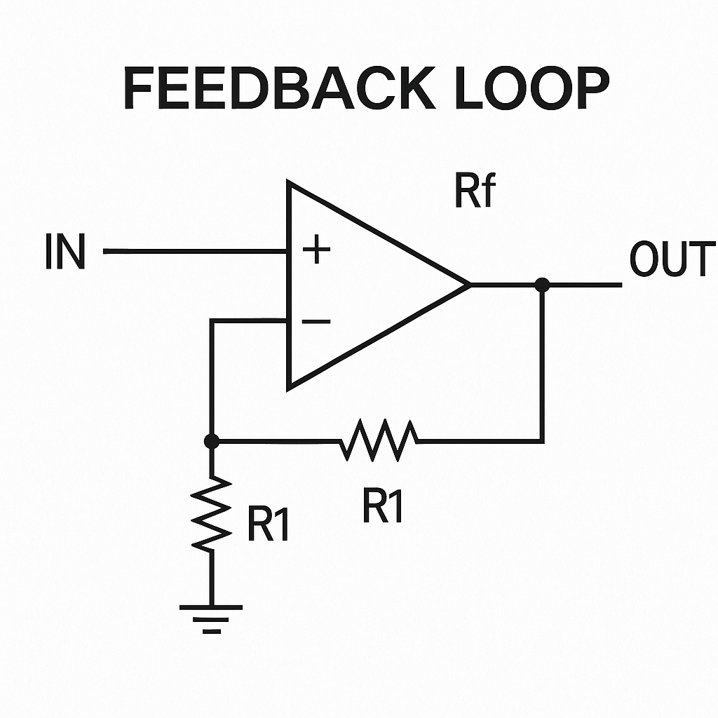
This non-inverting op-amp circuit models a behavioral feedback loop:
- Input (IN) drives the op-amp’s non-inverting (+) input.
- Output (OUT) feeds back to the inverting (–) input through Rf.
- A resistor R1 ties the inverting node to ground, setting the loop’s reference.
Gain (Escalation):
Gain = 1 + (Rf/R1).
Increasing Rf amplifies the loop, representing rumination intensifying.
Stabilization (Resistance):
R1 provides resistance against runaway feedback. A larger R1 reduces gain and stabilizes the loop, similar to damping repetitive thought.
In plain terms: the resistors Rf and R1 tune how strongly the system “re-plays” its output back as input, more feedback drives escalation, more damping adds stability.
Unless broken, feedback loops can run forever.
Add amplification? You get escalation.
Add resistance? You get stabilization.
Oscillator = Moods That Cycle
An oscillator turns a constant input into a repeated signal.
In people:
- Mood swings
- Creative bursts
- Repetitive behavior
- Anxiety flare-ups
Diagram: Emotional Oscillator

[Power] ──▶ [Oscillator Circuit] ──▶ [Up / Down Mood Output]
This schematic uses a 555 timer in astable (oscillator) mode. The constant “Power” (VCC) charges and discharges capacitor C1 through resistor R1, creating a repeating voltage ramp at the threshold node. “Output” toggles high and low each charge/discharge cycle, modeling “Up/Down Mood” swings. In people, this mirrors how a steady energy source (stress, stimuli) can produce cyclical emotional states like mood swings or anxiety bursts.
Oscillators often interact with feedback loops to create complex patterns like depression cycles or stress-response loops.
Latch = Memory That Stays On
A latch remembers a state even after the signal is gone.
In behavior:
- Holding a grudge
- Storing a lesson
- Remaining in a “mode” (alert, withdrawn, defensive)
Diagram: Emotional Latch
[Trigger] ──▶ [Set] → LATCH → [Stay in State]
[Reset Signal] ──▶ [Reset]
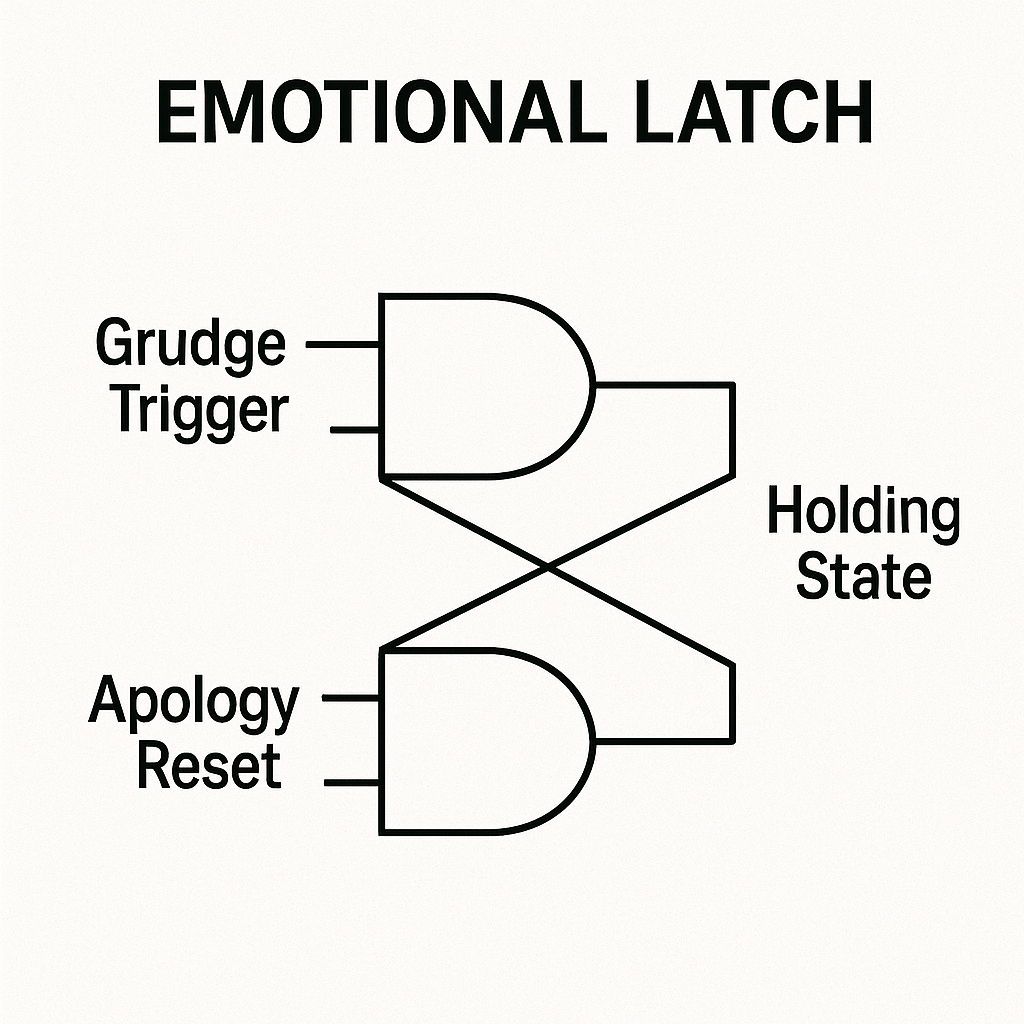
This SR latch uses two NOR gates:
- Grudge Trigger sets the latch: a single upset event locks in the Holding State output, modeling how grudges or lessons persist.
- Apology Reset clears it: a ritual or apology injects a reset signal to release the held state, allowing emotional recovery.
The cross-coupled feedback ensures the state remains latched until explicitly reset, mirroring real behavioral memory loops.
Latches must be reset, which is why apologies, rituals, or changes in context are often required to move on emotionally.
Composite Example: “Overreaction After Delay”
Imagine someone feels slighted. They don’t respond at first (RC delay). They replay it for days (feedback loop). Then they explode unexpectedly.
Full Diagram:
[Slight] ──▶ [RC Delay] ──▶ [Feedback Loop] ↻
                                 ↓
                             [Overreaction Output]
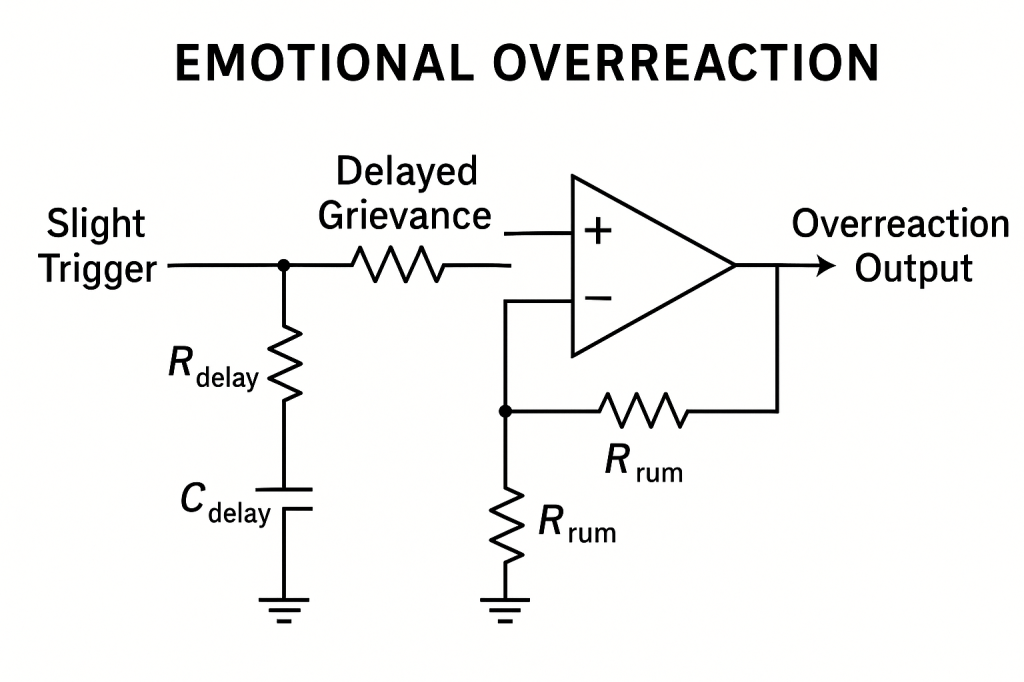
- Slight Trigger → RC Delay: A resistor Rdelay and capacitor Cdelay form a delay. The slight insult charges the cap slowly, no immediate response.
- Delayed Grievance → Rumination Loop: The delayed voltage feeds the op-amp comparator with a feedback network Rrum and the lower resistor) that causes oscillation, modeling constant replay and buildup of emotion.
- Overreaction Output: Once the internal loop reaches threshold, the comparator output suddenly swings high, producing an overreaction.
This circuit shows that what seems like an irrational emotional outburst follows precise timing (RC delay) and feedback (rumination), making the behavior logically predictable.
This isn’t irrational. It’s logical, once you see the timing.
Real-Life Applications
Timing circuits help us model:
- Why people take time to forgive (RC + latch)
- How trauma loops can be broken (feedback gate + clamp)
- How attention works (oscillator control + memory)
By understanding how time shapes behavior, we can:
- Design better communication
- Diagnose unhealthy loops
- Build therapeutic systems with timing logic
Part 6: Feedback Loops – Why We Get Stuck, Spiral, or Grow
“It’s not the input that traps us. It’s the loop. A memory replayed, a habit reinforced, a belief echoed. Feedback is the ghost in the circuit, and sometimes, the soul.”
We’ve explored signals, logic, and timing. Now we enter one of the most powerful, and dangerous, constructs in any system: the feedback loop.
In electronics, feedback changes the future behavior of a system based on its output. In humans, it’s how we:
- Reinforce a belief
- Spiral into obsession
- Cement trauma
- Build confidence
- Stabilize identity
- Repeat patterns
Feedback is what makes behavior recursive, evolving, or self-trapping. Let’s break it down.
What Is Feedback?
Feedback is when the output of a system loops back into its input.
It comes in two major forms:
- Positive Feedback: Amplifies the signal
- Negative Feedback: Damps or stabilizes the signal
Both are essential. One fuels change, the other provides control.
Positive Feedback = Escalation, Obsession, or Growth
In positive feedback, the more you output, the stronger the next input becomes.
Human Examples:
- Addiction
- Rage spirals
- Echo chambers
- Confidence growing with success
Diagram:
[Input] ──▶ [Amplifier] ──▶ [Output]
                         ↑         ↓
                       ↺ Feedback Loop
Explanation:
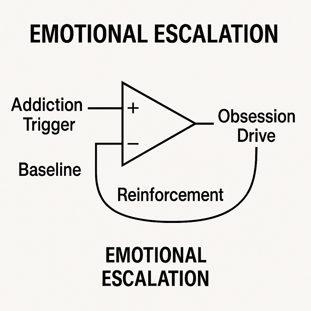
- Addiction Trigger (+): The initial impulse enters the non-inverting input of the op-amp.
- Baseline (–): The inverting input holds a reference level.
- Obsession Drive (Output): The op-amp’s output reflects the amplified stimulus.
- Reinforcement (Feedback): A loop from the output back to the inverting input raises its reference, increasing the next cycle’s drive.
This 2-input op-amp configuration models how each output increment strengthens the next input, producing runaway escalation seen in addiction, rage spirals, or confidence growth unless a limiting mechanism is introduced.
Unless capped, positive feedback leads to runaway behavior, or collapse.
Negative Feedback = Regulation, Reflection, Healing
In negative feedback, the output pushes back against the input, correcting or limiting it.
Human Examples:
- Self-awareness
- Emotional restraint
- Balanced thinking
- Cultural norms
Diagram:
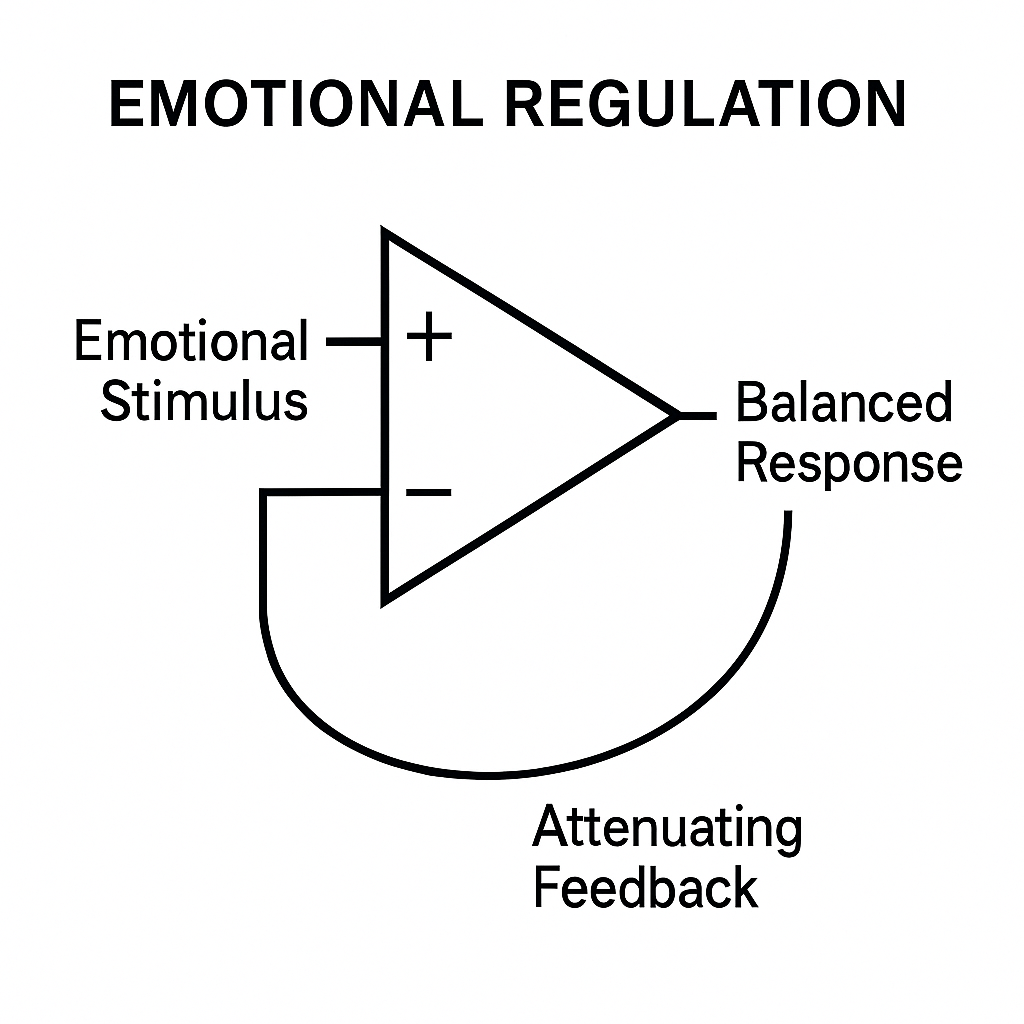
[Input] ──▶ [Processor] ──▶ [Output]
                        ↑         ↓
                 ←───── Attenuating Feedback
Explanation:
- Emotional Stimulus (non-inverting input +): The incoming impulse (stress).
- Attenuating Feedback (inverting input –): The output loops back to suppress excess, modeling self-awareness and restraint.
- Balanced Response (output): The corrected signal represents regulated emotion or thought.
This negative-feedback op-amp ensures homeostasis, mirroring how our mind or culture checks extremes and maintains balance.
Negative feedback creates homeostasis, like your body regulating temperature, or a mind pausing to consider consequences.
Composite Example: The Rumination Trap
A thought (“I’m not good enough”) loops with emotion → creates more evidence → confirms the thought → repeats.
This is a positive feedback loop with no break.
Rumination Loop Diagram:

[Insecurity Thought] ──▶ [Emotion Amplifier] ──▶ [Behavior Output]
                                          ↑                      ↓
                                       ←─────── Feedback Confirming Belief
Explanation:
- Insecurity Thought (non-inverting + input): The core negative belief enters and is amplified.
- Baseline Belief (inverting – input): Represents existing worldview or self-image as a reference.
- Behavior Output: The amplified emotion drives actions or mental loops.
- Confirming Belief (feedback): The output feeds back into the baseline belief, shifting it to reinforce the insecurity.
By using both op-amp inputs, this diagram shows how rumination traps the mind: each cycle amplifies negative thoughts and cements them as new “baseline,” creating an unbroken loop of self-reinforcement.
It builds a fortress of self-reinforcing signals, a belief trap.
Breaking the Loop: Insert Logic or Delay
To stop a feedback loop, you must:
- Clamp the loop (limit the signal)
- Insert logic (new conditions)
- Delay the signal (RC or memory insertion)
- Reset the latch (new state)
Break Diagram:
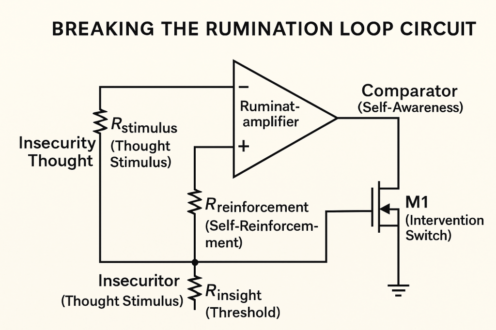
[Loop] ──▶ [Feedback]
         ↓
    [Comparator or Clamp] ──▶ STOP
Explanation:
- Rstimulus (Thought Stimulus): Models the initial insecurity triggering rumination.
- Rumination Amplifier (+ input): Amplifies the thought; feedback via Rreinforcement sustains the loop (self-reinforcement).
- Rinsight (Threshold): Sets the level for intervention (insight).
- Comparator (Self-Awareness): Compares amplifier output to the insight threshold.
- M₁ (Intervention Switch): When comparator output exceeds threshold, M₁ conducts, clamping the feedback node to ground and breaking the loop—analogous to an insight or therapy interrupting negative cycles.
This is what therapy, insight, or compassion can do, interrupt the recursion.
Feedback Builds Growth
Positive feedback isn’t always bad. It’s also how we:
- Learn (success reinforces attempts)
- Heal (kindness creates openness)
- Build culture (shared values strengthen behavior)
Growth Loop:

[Effort] ──▶ [Success] ──▶ [Confidence]
                      ↑           ↓
                   ←───── Feedback Motivation
Explanation:
- Effort → Rₑff: Your actions feed the success node.
- Success (non-inverting +): The moment of achievement.
- R₍fb₎ (Feedback Motivation): Confidence output loops back, boosting the next effort.
- Confidence (output): The built-up self-belief that drives further action.
- Ground Reference (inverting –): Sets a stable baseline.
This positive feedback circuit shows how structured loops of effort and reinforcement can reliably grow confidence, learning, healing, and cultural building, when properly balanced.
The key is structure. Without checks, loops collapse. With balance, loops evolve.
What You Can Build With Feedback Circuits
- Therapy models
- Economic bubbles
- Political polarization
- Habit tracking systems
- Reinforcement learning
- Social trust webs
Feedback is the engine of continuity, and sometimes, of entrapment.
Part 7: Burnout, Collapse, and Systemic Overload – When Circuits Overheat
“Every system has a limit. Push it too hard for too long, and it doesn’t just slow down, it fails. The same is true for machines, minds, and civilizations.”
Welcome to the failure state.
So far, we’ve built systems that respond, delay, remember, and loop. But every system, no matter how intelligent or beautiful, has a breaking point. We now model burnout, breakdown, and collapse as predictable circuit behaviors, not random chaos.
Whether it’s:
- A person exhausted by emotional load
- A company overwhelmed by scale
- A culture cracking under contradiction
- A body pushed beyond endurance
These can all be drawn, understood, and prevented using schematic logic.
Systems Fail for One of Three Reasons:
- Overload (Too much input or current)
- Feedback Explosion (Uncontrolled amplification)
- No Reset Path (Stuck in a permanent ON state)
Let’s build each.
1. Overload = Burnout
Too much current through a circuit causes heat. In people, this is:
- Working without rest
- Emotional flooding
- Constant crisis response
The resistor (your boundary) starts heating. The capacitor (your emotional memory) saturates. Eventually, the whole circuit fails.
Burnout Diagram:

[Constant Input] ──▶ [Resistor (Fatigue)] ──▶ [Capacitor (Emotional Memory)]
                                  ↓
                             [Heat = Stress]
                                  ↓
                          → [Threshold Exceeded] → Shutdown
Explanation:
- Constant Input → Fatigue (Resistor): Continuous demands stress your boundary, causing “Heat = Stress” at the resistor node.
- Emotional Memory (Capacitor to Ground): The capacitor stores the emotional load; saturation represents emotional exhaustion.
- Comparator (+ input at resistor-cap node, – input at Threshold): Monitors stress level.
- Shutdown (Comparator output): When stress exceeds a threshold, the comparator triggers shutdown, analogous to burnout resulting in depression, withdrawal, or numbness.
Result: Depression, withdrawal, numbness.
2. Feedback Explosion = Institutional Collapse
A feedback loop with no limiter becomes a runaway train. In systems:
- A lie repeated becomes a truth.
- Inflation rises faster than policy adjusts.
- A leader becomes unchecked.
Eventually, the loop destabilizes the system.
Collapse Diagram:

[Signal] ──▶ [Amplifier] ──▶ [Output]
                         ↑         ↓
                     ↺ Feedback
                          ↓
                 ↛ No Clamp = Infinite Gain
Explanation:
- Signal → (+) Input: The initial message or policy.
- Feedback → (+) Input Loop: The output directly reinforces the non-inverting node without any resistor or clamp, causing exponential amplification.
- (–) Input → Ground: Fixed reference, ensuring all gain is positive feedback.
- No Clamp = ∞ Gain: Without limiting, the amplifier saturates instantly, modeling how unchecked repetition leads to institutional collapse.
Result: The system eats itself. Often fast.
3. No Reset = Emotional Deadlock
Some circuits need a reset signal to return to baseline. Without it?
- You stay in fear even after the threat is gone.
- A belief persists despite being disproven.
- A policy stays in effect long after its relevance.
This is a latch stuck ON.
No Reset Diagram:
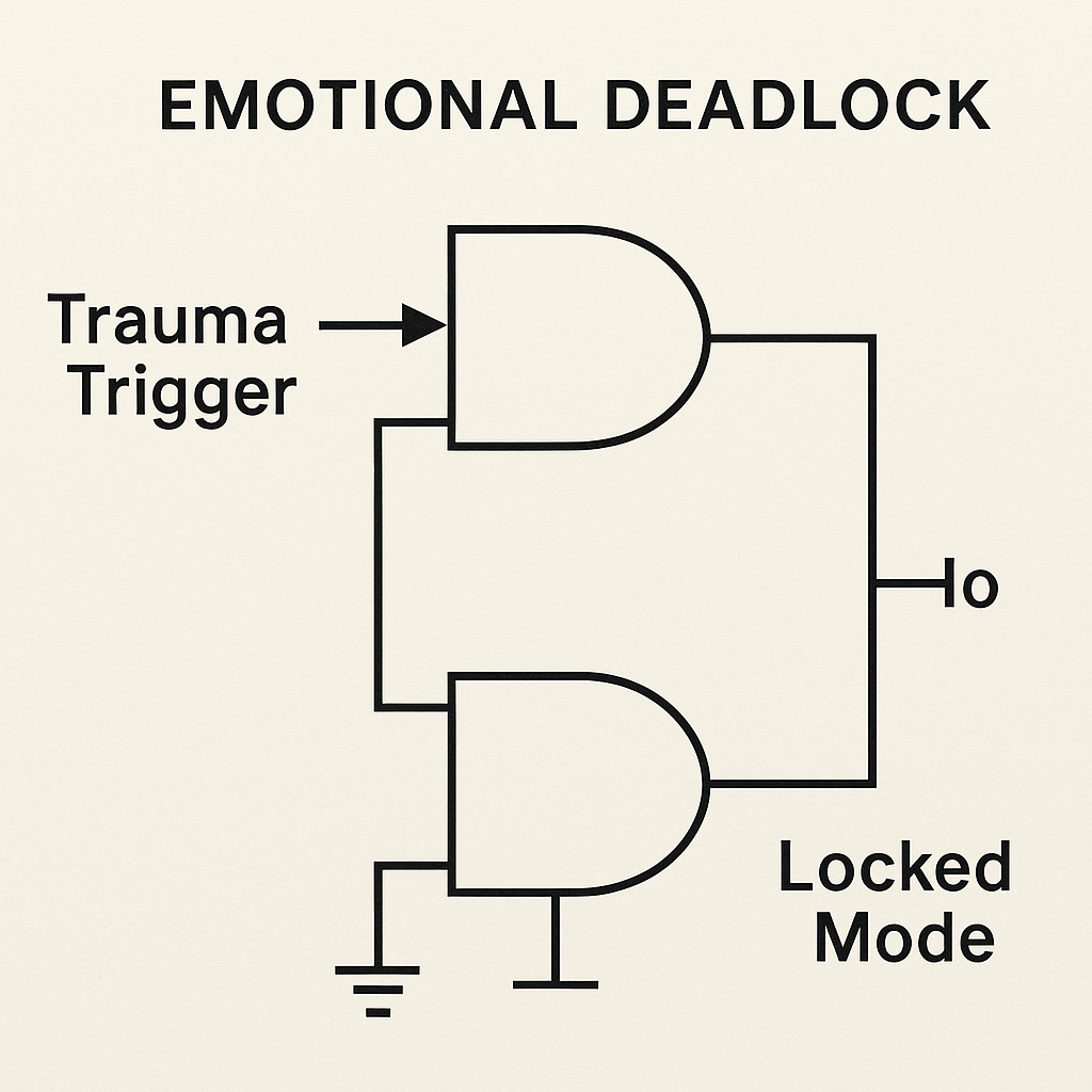
[Trigger] ──▶ [Set Latch] → [Stay in State]
                 ↳ (No Reset Path) → Frozen Mode
Explanation:
- Trauma Trigger → Set Input: A single trauma event sets the latch via the top NOR gate.
- Reset Input Tied Low: The lower gate’s input is grounded (no reset path), so the latch cannot clear.
- Locked Mode (Output): Once set, the cross-coupled NOR gates hold the output high indefinitely, modeling persistent fear, PTSD, or institutional inertia when no reset mechanism exists.
Result: PTSD, institutional inertia, cognitive rigidity.
Building Failsafes
Smart systems include protection:
- Clamps: Limit signal strength (stress management)
- Fuses: Break the loop if conditions become unsafe
- Cooldown Timers: Prevent overuse (rest, rituals)
- Manual Reset Buttons: Therapy, confession, transition
Diagram: Burnout-Protection Subcircuit
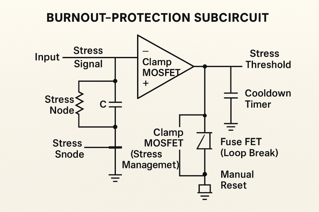
[Input] ──▶ [Comparator]
          ↓       ↘
   If > Threshold    Clamp or Reset → Safe State
Explanation:
- Stress Signal Node: A resistor and capacitor form the stress-sensing node, modeling boundary and memory of emotional load.
- Comparator (Clamp MOSFET): When stress exceeds the Stress Threshold, the comparator output turns on the clamp MOSFET, shunting excess stress to ground, mimicking stress management techniques.
- Fuse FET (Loop Break): The comparator output also opens the Fuse FET in the feedback path, breaking the burnout loop, analogous to a hard break like a fuse.
- Cooldown Timer: An RC network holds the comparator input low for a set time, preventing immediate re-trigger, models rest or recovery.
- Manual Reset Button: A push-button discharges the stress node, resetting the circuit, equivalent to therapy, confession, or deliberate context change.
This subcircuit integrates clamps, fuses, timers, and manual reset to ensure safe operation and prevent runaway stress or burnout.
Every stable system has a way to shut down safely.
Personal Application
Use this model to:
- Understand your burnout cycles
- Design daily routines with feedback control
- Build in reflection time as a reset pulse
- Set emotional limits like thermal sensors
No system runs infinitely. Not even you. But with the right schematic, you don’t have to burn out, you can reboot.
Part 8: Emotions as Circuits – The Electric Self
“What if love was a feedback loop? What if anger was an overloaded gate? What if grief was a capacitor still slowly discharging?”
Emotion isn’t magic. It isn’t mystical. It’s powerful, yes, but it follows rules.
We now begin mapping specific emotions using the tools we’ve developed: voltage (intensity), current (action), resistance (hesitation), capacitors (memory), diodes (trust), and logic gates (conditions). What emerges is not just insight, but architecture, a buildable emotional self.
Let’s wire up the psyche.
1. Anger = High Voltage + Short Resistance
Anger is fast. It builds pressure (voltage) and needs a release path. If resistance is low, the signal explodes outward. If resistance is high, it builds pressure, and may burst later.
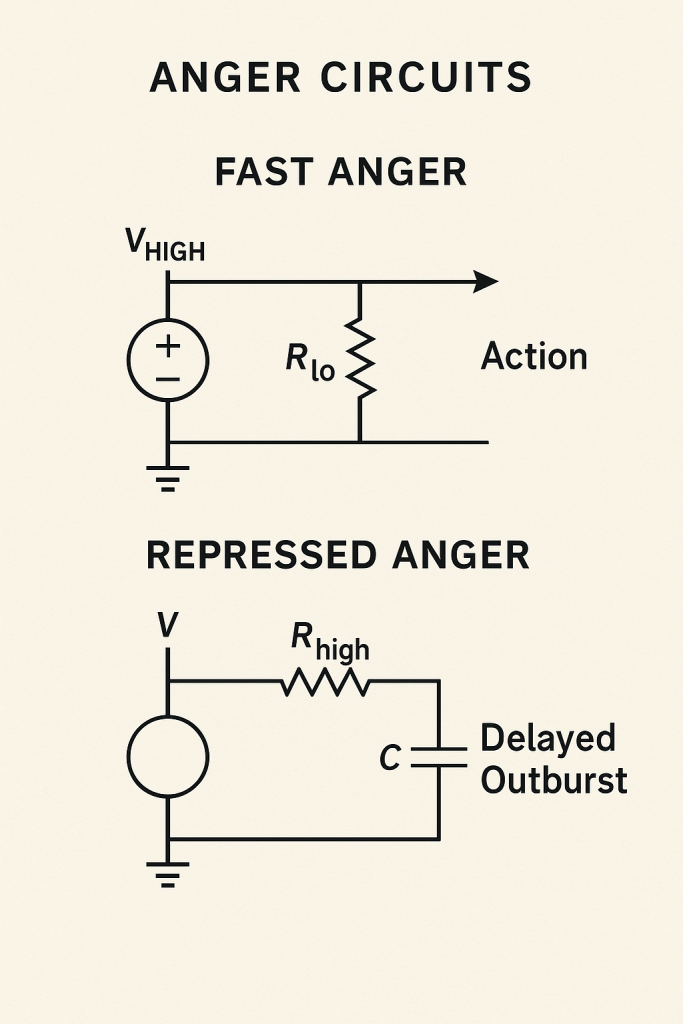
Diagram: Fast Anger
[Trigger] ──▶ [High Voltage Source] ──▶ [Low Resistor] ──▶ [Action]
Diagram: Repressed Anger
[Trigger] ──▶ [Voltage] ──▶ [High Resistance] ──▶ [Capacitor]
                                             ↓
                                       → Delayed Outburst
Explanation:
- Fast Anger:
- Vhigh (High Voltage Source): Rapid rise in emotional pressure.
- Rₗₒ (Low Resistance): Minimal boundary allows immediate release, instant action.
- Repressed Anger:
- V (Voltage Source): Emotional pressure builds.
- Rhigh (High Resistance): Strong boundary slows the flow.
- C (Capacitor): Stores pressure; once saturated, it discharges later as a delayed outburst.
By adjusting voltage (intensity) and resistance (boundary), anger’s timing and expression can be predicted and modulated.
Anger isn’t irrational. It’s electrical. And it can be modulated.
2. Trust = Forward-Biased Diode
Trust is a directional gate. If it’s forward-biased (you’re open), connection flows. If it’s reverse-biased (past betrayal), it blocks.
Diagram: Trust Diode

[Connection Attempt] ──▶ [Diode (Trust Gate)] ──▶ [Bond]
                   ←── (Rejection if Reverse Biased)
Explanation:
A diode only conducts when forward-biased, here, when a “Connection Attempt” meets the “Trust Gate,” it passes through and forms a “Bond.” If the diode is reverse-biased (past betrayal or mismatch), it blocks current, causing rejection. Applying too high a voltage across a reverse-biased trust diode leads to breakdown, analogous to pushing too hard and causing hurt or withdrawal. Trust, like a diode, must be forward and within limits to maintain healthy connections.
Too much voltage (intensity) across a reverse-biased trust diode? Breakdown.
This is why pushy people cause withdrawal, and gentle signals build bridges.
3. Grief = Discharging Capacitor
Grief is emotional energy with nowhere to go. It’s a capacitor charged by connection, now slowly discharging through resistance and time.
Diagram: Grief Decay

[Loss Event] ──▶ [Capacitor (Love Memory)]
                        ↓
             ──▶ [Slow Resistor] ──▶ [Tears, Silence, Meaning]
Explanation:
- Loss Event → Cmemory: Grief begins by charging the emotional memory capacitor with the energy of loss.
- Rdecay to Ground: The slow resistor represents how grief discharges over time, governing the rate of emotional release.
- Tears / Silence / Meaning: The current through Rdecay manifests as expressions of grief, tears, quiet reflection, and eventually finding meaning.
Like an RC discharge, grief holds its charge until it naturally decays, leaving only echoes in memory.
You don’t “get over” grief. You discharge it. The circuit holds until it doesn’t. And then… only echoes.
4. Love = Feedback Amplifier Between Nodes
Love flows back and forth. Each loop builds more signal, more connection. It’s feedback, but cooperative.
Diagram: Reciprocal Love Loop

[You] ──▶ [Signal] ──▶ [Them]
   ↑                         ↓
 ←────── [Return Signal] ←──────
           ↺ Amplifies Over Time
Explanation:
- You → (–) Input of Love Amplifier: Your initial expression of care feeds into the negative input.
- Love Amplifier: A two-input op-amp symbol with correct + (non-inverting) and – (inverting) labels.
- Them (Output): The amplified signal reaches the other person.
- Return Signal → (+) Input: Love returned from them loops back positively, building stronger connection.
- Amplifies Over Time: Continuous back-and-forth feedback increases bond and becomes part of identity.
Break the loop? Signal fades. Sustain it? It becomes identity.
5. Anxiety = Oscillator Triggered by Uncertainty
Anxiety is repetitive thought without closure. Like a buzzing oscillator, it flips between worry and silence, never settling.
Diagram: Anxiety Oscillator
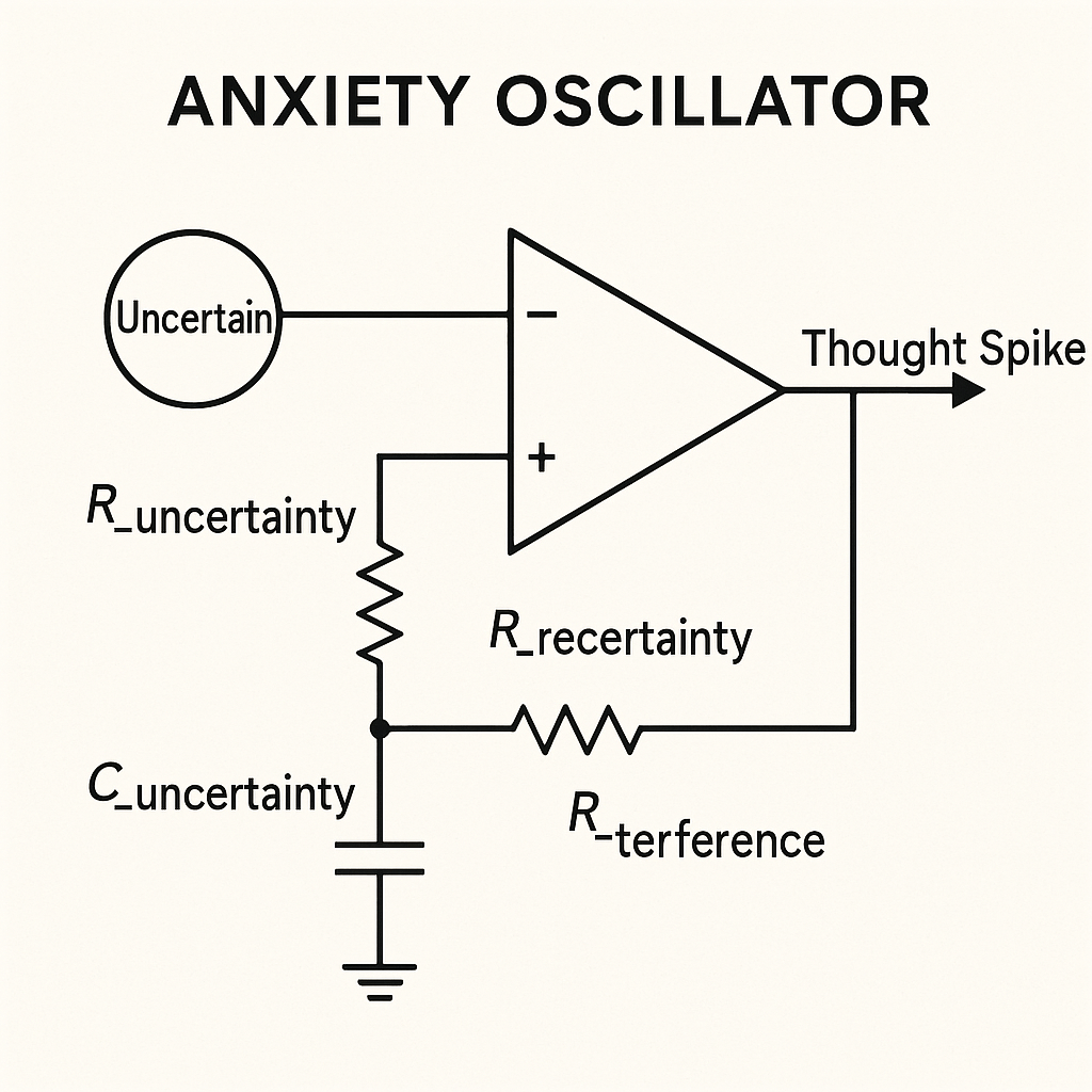
[Uncertainty] ──▶ [Oscillator Circuit] ──▶ [Thought Spike]
                                     ↻
Explanation:
- Uncertainty (– input through no resistor): Acts as the driving voltage for the oscillator.
- R_uncertainty & C_uncertainty (– input network): The resistor–capacitor pair sets the oscillation period, representing the cycle of worry and forgetfulness.
- Op-Amp Relaxation Oscillator: Uses the + input’s feedback network, R_feedback (R_recertainty) and R_reference (R_terference), to create hysteresis and toggle states.
- Thought Spike (output): Each oscillation yields a spike of anxious thought.
Without damping (clamp or delay), this circuit will produce continuous worry cycles. Introducing a clamp or RC delay can slow or halt the oscillations, modeling anxiety relief strategies.
Add feedback? It intensifies. Add a clamp or delay? You can calm it.
The Emotional Machine
You’re not one feeling. You’re a circuit board:
- Trust gates
- Love loops
- Grief capacitors
- Anger spikes
- Anxiety oscillators
- Forgiveness delays
And like all boards, you can diagnose, design, and debug.
Why This Matters
When you draw emotions like circuits:
- You stop pathologizing
- You start understanding
- You can build systems that reflect real inner logic
- You can teach empathy, not as morality, but as engineering
And you begin to see that emotional intelligence is not soft, it’s precise.
Part 9: Relationships as Circuits – Wiring for Love, Conflict, and Repair
“A relationship isn’t a mystery, it’s a connection. A flow of signal, sometimes stable, sometimes noisy. Love, like current, must flow both ways. And like all circuits, it can be interrupted, overloaded, rerouted, or rebuilt.”
Previously, we saw how individual emotions are circuit components, trust as a diode, grief as a capacitor, anxiety as an oscillator. Now we zoom out. What happens when two or more of these systems connect?
Welcome to relationship circuitry, where feedback, synchronization, and connection determine whether the signal flows… or shorts.
1. Reciprocal Relationships = Bi-Directional Feedback
A healthy connection flows in both directions:
- You signal → they respond → you amplify
- The relationship becomes a loop of care, trust, and reinforcement
Diagram: Mutual Loop
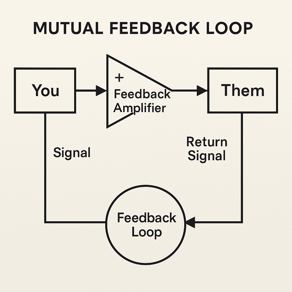
[You] ──▶ [Signal] ──▶ [Them]
   ↑                         ↓
 ←────── [Return Signal] ←──────
           ↺ Feedback Loop
Explanation:
- You → (+) Input of Feedback Amplifier: Your initial signal of care or communication.
- Feedback Amplifier: Acts like a non-inverting amplifier, sending the strengthened signal to “Them.”
- Them → Return Signal: The response from them loops back into the circuit’s feedback path.
- Feedback Loop (circle): Represents the ongoing, mutual reinforcement—each cycle amplifies trust, understanding, and connection.
Disrupting or interrupting this bidirectional feedback weakens the relationship, while sustaining it deepens the bond and makes it part of both identities.
Disrupt the loop? Signal weakens.
Interrupt feedback? Disconnection begins.
2. Codependency = Shared Oscillator Without Autonomy
Codependent relationships act like a synchronized oscillator:
- One person’s emotional state flips the other’s
- Identity merges
- Self-regulation weakens
Diagram: Synchronized Loop
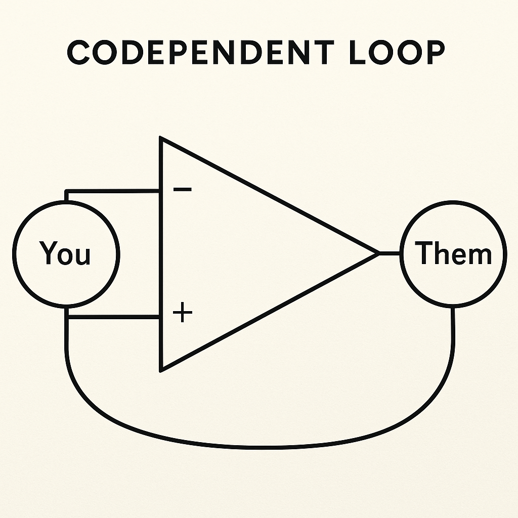
[You] ⇄ [Them]
↻ Loop Signal Oscillates Based on Shared Input
Explanation:
- You → + Input: Your emotional signal feeds the non-inverting input.
- Them (Output): The op-amp’s output drives their emotional response.
- Feedback Loop to – Input: Their response loops directly into the inverting input, forcing both states to oscillate together.
Without any resistor or capacitor (no buffer or regulation), “You” and “Them” are locked in a shared circuit, codependency with no autonomy.
There’s flow, but no resistance, no regulation, no space.
Healthy relationships have buffers.
3. Conflict = Signal Collision + Overload
When expectations differ or values clash, signal conflict results.
This can cause:
- Voltage spikes (emotional blowups)
- Feedback inversion (you do the opposite of what they want)
- Line noise (miscommunication)
Diagram: Conflict Gate
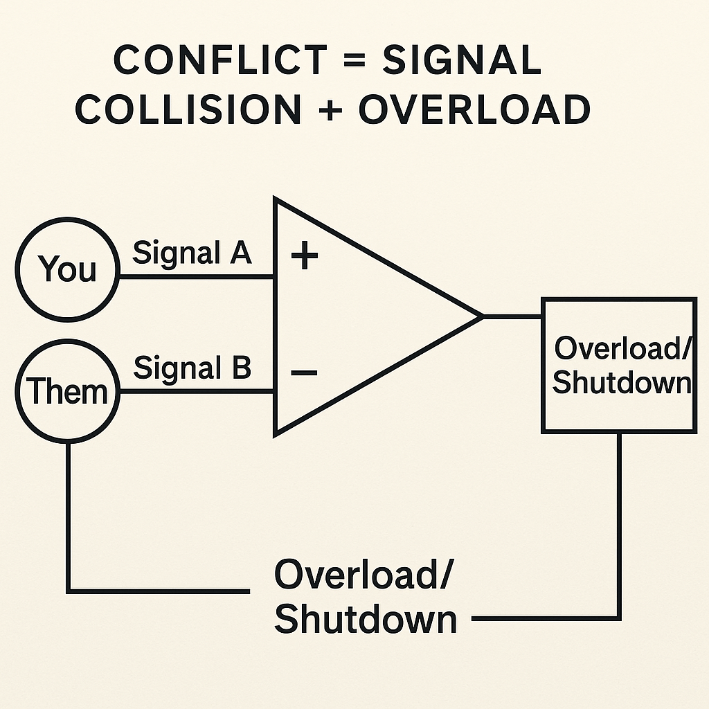
[You] ──▶ [Signal A]
[Them] ──▶ [Signal B]
             ↓
        A ≠ B → Comparator → Overload or Shutdown
Explanation:
- Signal A (You → + Input): Your expectations or needs enter the comparator’s non-inverting input.
- Signal B (Them → – Input): Their expectations enter the inverting input.
- Comparator Output: When A ≠ B, the comparator switches state, signaling conflict.
- Overload/Shutdown: If the mismatch exceeds the comparator’s hysteresis (no clamp), the output triggers overload or shutdown, analogous to emotional blowups, resistance to change, or policy paralysis requiring a new rule or clamp.
Conflict isn’t failure, it’s a diagnostic event. The circuit needs a new rule or clamp.
4. Forgiveness = Reset Signal After Stored Pain
Forgiveness is not erasure, it’s a manual reset after charge buildup.
Pain (emotional charge) must discharge, then intentional logic resets the state.
Diagram: Forgiveness Circuit

[Hurt] ──▶ [Capacitor] ──▶ [Emotional Load]
                             ↓
                 [Apology + Time] → Reset Latch → New State
Explanation:
- Hurt → Capacitor (C, Emotional Load): Charged by a painful event, representing accumulated emotional energy.
- S Input (Set): The capacitor node feeds the S input of the SR latch (top NOR gate), latching the hurt state.
- R Input (Reset): A manual switch actuated by “Apology + Time” grounds the R input of the latch (bottom NOR gate), clearing the hurt state.
- New State (Q): The latch output transitions to a healed state once reset, demonstrating that forgiveness is an active reset requiring intentional input, not passive discharge.
Forgiveness is active circuitry, not passive forgetting.
5. Attachment Styles = Default Wiring Patterns
Different people wire differently from the start:
| Style | Circuit Profile |
|---|---|
| Secure | Bi-directional feedback with buffers |
| Anxious | Oversensitive oscillator, low delay |
| Avoidant | High input resistance, signal clamp |
| Disorganized | Feedback chaos, short circuits |
These aren’t fixed, they’re schematics you can redesign over time.
Building Better Circuits
Good relationships include:
- Buffers: space between signals
- Clamps: emotional limits
- Delays: time before reaction
- Gates: clear rules for input/output
- Feedback: real responses
- Reset paths: for conflict repair
Think of it like building a communication device that runs on emotion, memory, attention, and care.
Applications
- Couples therapy diagrams
- Communication flow design
- Relational logic
- Family dynamic modeling
- Ritual design for repair
- Friendship scaffolding for digital tools
You can now see the architecture of intimacy, and improve it.
Part 10: Empathy, Projection, and Communication Gates – Translating Emotional Signals
“Every emotion is a signal, but not every signal gets through. Some are amplified, others distorted, some blocked entirely. Empathy is how we tune to another’s frequency. Miscommunication is when the signal breaks.”
As we’ve built emotional and relational circuits, one force quietly animates them all: communication. Not just talking, but signal transfer. Not just hearing, but translation. And not just feeling, but empathy, the ability to interpret someone else’s internal voltage in your own circuit logic.
We explore how signals move between minds, and where they get converted, lost, or distorted.
1. Communication = Signal Encoding + Transmission + Decoding
In electronics, a communication system has at least three parts:
- Encoder: Converts message into signal
- Channel: Transmits signal
- Decoder: Reconstructs the message
Same in human interaction:
- You feel something (internal voltage)
- You say something (output signal)
- They interpret it (their input logic)
Diagram: Basic Communication Circuit

[You] → [Encoder] → [Channel] → [Decoder] → [Them]
Explanation:
- You provide the internal message as a voltage.
- Encoder converts that voltage into a standardized signal.
- Channel represents the medium carrying the signal, with potential noise or loss.
- Decoder reconstructs the original message from the signal.
- Them receives the interpreted message.
Any break in encoder, channel, or decoder scrambles communication, just like a damaged line or misconfigured circuitry.
Break any part, and the message is scrambled.
2. Empathy = Signal Transduction Across Emotional Barriers
Empathy is like a signal converter, it translates voltage from one person’s context into another’s understanding.
Just like converting analog to digital or AC to DC.
Diagram: Empathy Transducer

[Their Emotion] → [Transducer] → [Your Perception]
                           ↓
              (Filtered by experience + bias)
Legend & Notes:
- Transducer: Can be drawn as a small transformer symbol (two inductors with a coupling core) or as a differential amplifier block, this converts “Their Emotion” into a signal you can process.
- R + C to GND: Models how your prior experience (R) and unconscious bias (C) filter/shape the incoming signal before it reaches your conscious perception.
- Your Perception: The output of the transducer, modulated by the filter.
Failures occur if:
- The Transducer itself is broken (blocked by narcissism or unresolved trauma).
- The signal from “Their Emotion” is too weak to drive the transducer.
- The R + C filter overloads (too much bias or noise), drowning out the true signal.
3. Projection = Internal Signal Mistaken for External Input
Sometimes, we interpret our own signal as someone else’s. That’s projection.
You feel insecure → You think they dislike you.
It’s like internal noise leaking into the input channel.
Diagram: Projection Interference

[Your Emotion] ──┐
                 ↓
         [Input Interpretation]
                 ↑
         [Actual External Signal]
Explanation:
- Actual External Signal (– input): The real, external information you receive.
- Your Emotion → Rproj: A resistor injecting internal feelings into the non-inverting input.
- Op-Amp Summer: Combines external and internal signals, producing the “Input Interpretation” at the output.
- Input Interpretation (output): The distorted perception when internal noise (projection) leaks into the processing path.
This summing amplifier model shows how unchecked personal emotions corrupt objective input.
Projection distorts communication like a ground loop hum in an audio line.
4. Communication Gates = Conditional Expression
In real life, we don’t always say what we feel. There are logic gates filtering expression:
- “I’ll say this if I trust them”
- “I’ll speak up unless I feel shame”
Diagram: Expression Gate

[Emotion] ──▶ [AND Gate: Trust ∧ Safety] ──▶ [Verbal Output]
Explanation:
- Emotion (Input A): The primary drive to express.
- Trust & Safety (Input B): The required conditions for honest expression.
- AND Gate: Both inputs must be true to pass the signal.
- Verbal Output: The spoken message, only occurs if you feel safely trusted.
Gate failures can blur this:
- Fail-open: Outputs without proper conditions → blurting.
- Fail-closed: Blocks despite emotion → suppression.
This is how miscommunication arises, not from bad intent, but from gated pathways.
5. Signal Boosters = Repetition, Tone, Body Language
Some messages don’t land on the first try. We boost them:
- Volume
- Repetition
- Metaphor
- Emotion
These are amplifiers in the transmission chain.
Diagram: Boosted Message

[Signal] → [Amplifier: Tone + Context] → [Channel] → [Decoder]
Explanation:
- Signal (Input): The original message.
- Tone + Context (First Amplifier): Acts as a booster, volume, repetition, emotional framing.
- Channel (Resistor to Ground): Represents medium noise and attenuation.
- Decoder (Second Amplifier): Reconstructs and clarifies the boosted signal.
- Received (Output): The final interpreted message.
Just like radio, stronger signals travel better, especially across noisy lines.
Real-World Applications
- Therapy Models: Help clients build their own communication diagrams
- Couples Tools: Build visual circuits of “when I don’t feel heard”
- Cross-Cultural Systems: Model linguistic/emotional translation paths
- Education: Teach logic of miscommunication through signal loss diagrams
Insight
Empathy is engineering. It’s not mystical. It’s transduction, amplification, and alignment.
Miscommunication is mechanical. It’s not failure. It’s just a bad channel, a broken gate, a missing reset.
If we can draw it, we can fix it. Or better yet: design it right from the start.
Part 11: Group Dynamics and Swarm Logic – How Behavior Spreads in Crowds
“A single person is a signal. A group is a network. Behavior spreads not like thought, but like current, jumping from node to node, amplified, delayed, or inverted by the circuits that connect us.”
So far, we’ve explored the circuits of the self: emotion, logic, feedback, and communication. Now we scale up. What happens when multiple minds form a mesh? A collective. A crowd. A movement. A mob.
Now we explore group dynamics using schematic logic, how behaviors propagate, sync, escalate, and collapse through social circuits.
1. Groups Are Mesh Networks
Every person is a node. Every interaction is a connection. Each node:
- Processes its own input
- Reacts with delay or resistance
- Feeds signal to neighbors
Diagram: Social Mesh

[Person A] ⇄ [Person B] ⇄ [Person C] ⇄ [Person D]
       ↘                      ↑                   ↗
         [Person E] ⇄ [Person F] ⇄ [Person G]
In such a mesh, a single signal can ripple, depending on:
- Network density
- Connection strength
- Signal type (emotion, idea, command)
- Feedback loops
2. Social Cascades = Amplified Feedback Loops
Sometimes a behavior or emotion triggers a chain reaction.
Example: panic in a crowd.
Diagram: Panic Cascade

[Initial Signal] → [Amplifier] → [Person A]
                                 ↓
                         [Amplifier] → [Person B]
                                 ↓
                         ↻ Feedback → Exponential Spread
Explanation:
- Initial Signal: The first instance of panic.
- Amplifier: Each person (circle) amplifies the panic signal.
- Person A & Person B: Represent crowd members whose reactions fuel the loop.
- Feedback Loop: Person B’s response loops back to retrigger Person A, causing exponential spread.
This cascade model shows how panic or behavior can propagate rapidly through a group via amplified feedback loops.
No one fully understands what’s happening. But each person amplifies the previous one.
This is swarm logic.
3. Groupthink = Signal Clamping + Inverted Feedback
When consensus pressure is strong:
- Contradictory signals are clamped
- Individual input is ignored
- Only “approved” signals get through
This creates self-stabilizing false certainty.
Diagram: Groupthink Circuit
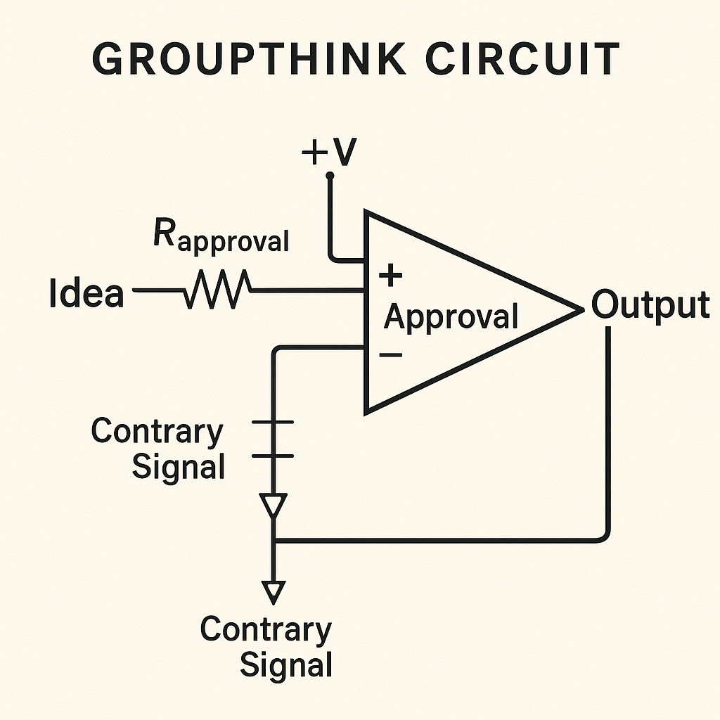
[Idea] → [Clamp Gate: Social Approval] → [Output]
               ↑
   [Contrary Signal] → BLOCKED
Explanation:
- Idea → R₍approval₎ → + Input: The original concept enters the approval amplifier.
- +V Pull-up: Social consensus pressure holds the approval node high.
- Diode‐Clamp on “Contrary Signal”: A diode to ground clamps approval low if a contrary view appears, blocking the node.
- AND Gate “Approval” (amplifier symbol): Requires approval node high to pass the idea.
- Output → Feedback Loop: The consensus output feeds back to reinforce social pressure.
- Flow: Without social approval (node clamped by contrary), the idea is blocked. The feedback loop then sustains the dominant signal, modeling groupthink.
This logic depicts how groupthink uses clamping of contrary views and inverted feedback to maintain false certainty.
4. Moral Panic = Oscillator with External Trigger
When outrage or fear cycles rapidly across nodes, you get a moral oscillator, a fast, escalating, looping emotional system.
Diagram: Moral Panic Oscillator
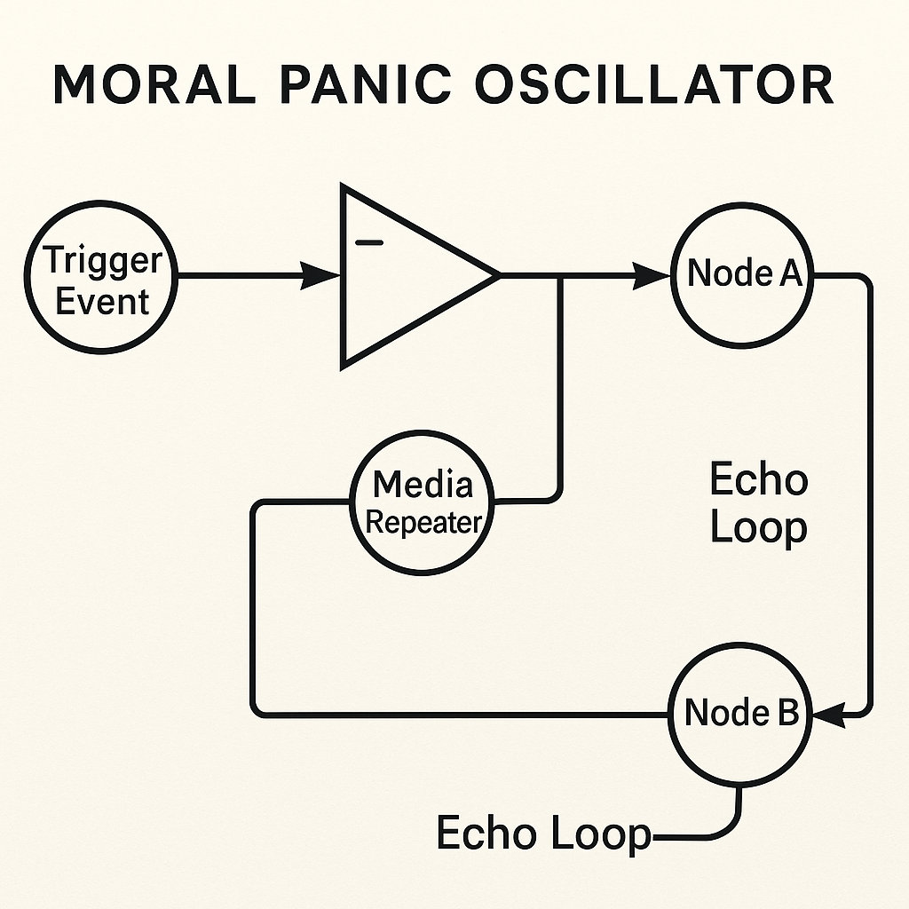
[Trigger Event] → [Amplifier] → [Node A]
                           ↓        ↑
                ↺ [Echo Loop] ← [Node B] ← [Media Repeater]
Explanation:
- Trigger Event → (+) Input of Op-Amp: The event drives the moral panic amplifier.
- Op-Amp Output → Node A: Early responders amplify the signal to the Media Repeater.
- Media Repeater → Node B: Broadcasts to a wider audience.
- Echo Loop: Feedback from Node B returns to the op-amp’s inverting input, sustaining oscillation.
- Loop Labels: Each echo path is marked to show repeated amplification and cycle reinforcement.
This isn’t just virality, it’s resonance. Certain networks are primed to oscillate.
5. Trend Propagation = Delayed Synchronization
Trends don’t hit all nodes equally. Some resist. Some delay. Others sync instantly.
Behavior spreads via:
- Peer influence (logic gates)
- Latent desire (capacitors)
- Social proof (comparators)
Diagram: Trend Sync Circuit

[Core Signal] → [Node A: Early Adopter] → [Node B: Follower]
                            ↘        ↘
                 [Comparator]   [Delay Buffer]
                            ↓
                  → [Node C: Resistant → Converts]
Explanation:
- Core Signal: The origin of the trend, splitting to both early adopter and comparator.
- Node A (buffer amplifier): Represents early adopters who immediately synchronize with the trend.
- Node B (follower): Receives the trend directly, then feeds into an RC delay network Rdelay + capacitor before reaching Node C.
- Comparator (op-amp): Compares early adopter signal with delayed follower signal to trigger resistant nodes.
- Node C (capacitor to ground): Initially resists the trend; once the delayed signal crosses threshold, it converts and joins the trend.
- The arrangement shows how peer influence, latent desire, and social proof synchronize over time, leading to eventual full-circuit trend adoption.
Eventually, the whole circuit synchronizes, until the next disruption.
Applications
- Model protest dynamics or populist surges
- Analyze marketing virality
- Simulate peer pressure in game design
- Design alert systems for institutions
- Identify nodes that can diffuse conflict instead of amplify it
Insight
A group is not just a collection of individuals. It is:
- A feedback field
- A synchronizing oscillator
- A behavior amplifier
- A delay buffer
- A signal web
Once you see people as a distributed system, you can stop reacting and start designing. You can guide, stabilize, or reroute.
Part 12: Conflict and Repair Architecture – Contradiction Gates, Apology Resets, and Peace Latches
“Conflict isn’t chaos. It’s a voltage clash, a logic error, a gate inversion. And repair? It’s not just kindness. It’s a circuit reset. A signal re-sync. A new path carved through an old loop.”
We’ve now built emotional engines, interpersonal logic gates, and group behavior networks. But no circuit runs clean forever. Contradiction, friction, and overload are inevitable.
Now we diagram conflict and repair as schematic systems. This isn’t just about arguments, it’s about how relationships break down and rebuild, from couples to communities to entire institutions.
1. Conflict = Contradiction at a Logic Junction
Conflict begins when two signals expect different outputs.
- Person A expects X
- Person B expects ¬X
- Result: contradiction gate is tripped
Diagram: Contradiction Conflict Gate
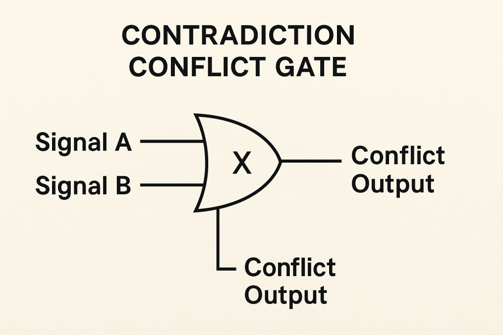
[Signal A] ──▶
             XOR ──▶ [Conflict Output]
[Signal B] ──▶
Explanation:
- Signal A & Signal B: Inputs to the XOR gate.
- XOR Gate (⊕): Outputs high only when exactly one input is true, representing conflict.
XOR gates only output 1 if inputs are different.
This is why compromise isn’t easy: it requires a new logic path.
2. Stalemate = No Reset Path
Some conflicts persist because there’s no way to reset the system:
- No apology
- No change in logic
- No interruption of the feedback loop
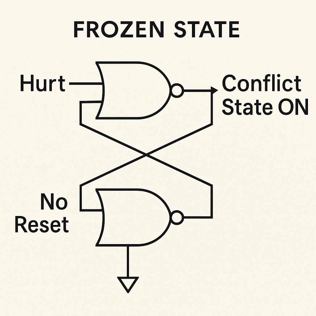
Diagram: Frozen State
[Hurt] → [Latch]
(No Reset Line) → Output = Conflict State ON
Explanation:
- Hurt → S input (NOR gate): A hurt event sets the latch and drives the conflict state.
- No Reset → R input (NOR gate tied to ground): Without a reset path, the latch cannot clear.
- Cross-Coupled Feedback: Output of each NOR gate loops back to the other’s input, sustaining the set state.
- Conflict State ON (Q): The latch remains locked in conflict until a reset is introduced.
Until a reset signal is introduced, the system remains locked in tension.
3. Apology = Reset Pulse + Logic Override
Apology isn’t just emotional. It’s mechanical:
- Injects a new signal into a locked circuit
- Opens a feedback gate
- Discharges stored hurt
- Allows a new logic path to form
Diagram: Apology Reset

[Conflict Latch] ←────┐
[Apology Signal] ──▶ [Reset Line]
                         ↓
                    [Neutral State]
Explanation:
- SR Latch IC Block: Represents a single IC with internal NOR gates.
- Hurt (S input): Sets Q high (“Conflict State”).
- Apology (R input): Sets Q high (“Neutral State”).
- Cross-Coupling: Internal NOR gates feed each other’s inputs (inside the IC), maintaining state until reset.
This latch illustrates how an apology pulse resets the conflict latch to neutrality.
No apology = no reset = permanent fault state.
4. Forgiveness = Controlled Discharge of Emotional Energy
Forgiveness isn’t forgetfulness. It’s voltage regulation:
- Stored pain in a capacitor
- Discharged through resistance
- Requires time, reflection, perspective
Diagram: Forgiveness Circuit
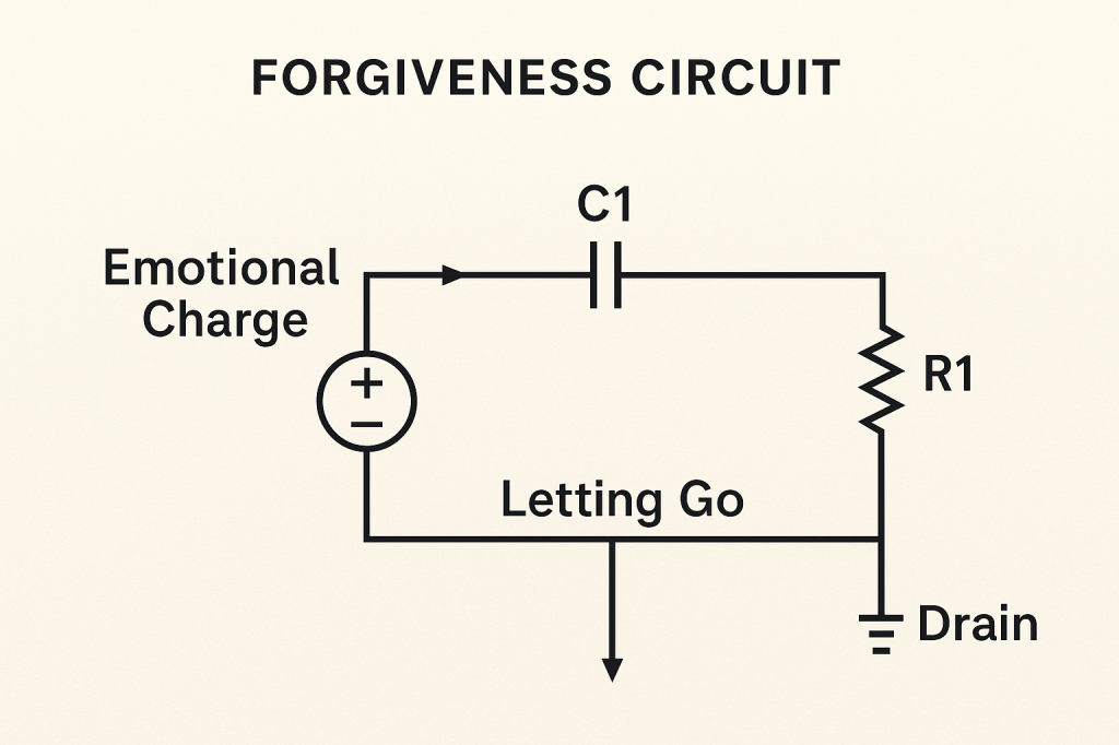
[Emotional Charge] → [Capacitor] → [Slow Resistor] → [Drain]
                                          ↓
                                Output = “Letting Go”
Explanation:
- Emotional Charge (voltage source): Represents stored pain charging C1.
- C1 (Capacitor): Holds the emotional energy.
- R1 (Resistor): Controls discharge rate, mapping to time, reflection, and perspective.
- Drain (Ground): The discharge endpoint.
- Letting Go (Output): The current leaving the capacitor through R1 over time.
Forgiveness is tuning R1 for an optimal rate: too small → shock; too large → grudge; just right → healthy release. Forgiveness is a discharge rate.
5. Peace = Re-synchronization After Divergence
Peace isn’t silence, it’s harmonic logic. A shared comparator finds new ground:
- Both parties revise signals
- A new agreement logic is stored
- The system stabilizes in a new configuration
Diagram: Peace Comparator

[Revised Belief A] ──▶
                     AVG COMPARATOR ──▶ [New Shared Logic]
[Revised Belief B] ──▶
Explanation:
- Revised Belief A (non-inverting +): Direct input representing one side’s updated perspective.
- RB (Belief Resistor): Weighs Revised Belief B before feeding the inverting input.
- Rfeedback: Connects the output back to the inverting input, providing negative feedback for stability and consensus reinforcement.
- New Shared Logic (output): The comparator’s output stores the agreed-upon ground, modeling peace as a newly stabilized configuration rather than a return to the old state.
Peace is not return to the old state. It’s emergence of a new one.
Application and Design
Use this model to:
- Diagnose relationship gridlock
- Build apology rituals into software or storytelling
- Train mediation or conflict-resolution systems
- Design cooperative agents with repair pathways
- Understand cultural or political reconciliation logic
Insight
Every fight is a signal problem. Every resolution is a logic repair.
If we build relationships as sophisticated systems, we stop blaming, and start tuning.
There is no circuit that can’t be redrawn, if we know where to send the current.
Part 13: Rituals, Culture, and Shared Circuits – Encoding Meaning into Systems
“Culture is a circuit drawn across time. Ritual is the logic gate of memory. Meaning is not abstract—it’s a signal reinforced until it becomes structure.”
Previously, we explored internal logic, emotional dynamics, group behavior, and conflict repair. Now we enter the deep substrate of human systems: culture.
Culture is not just belief. It’s patterned behavior, encoded memory, and collective feedback loops. It’s how a society wires its circuits to ensure emotional regulation, social bonding, and systemic stability.
And rituals are the operating systems, sequences of action that serve as reset pulses, logic synchronizers, and storage systems.
1. Culture = Persistent, Shared Circuitry
Culture is a distributed, recursive logic system shared by many nodes (people). It stores:
- Value structures (what matters)
- Norms (expected signal behavior)
- Emotional response templates
It evolves not by command, but by repetition, feedback, and encoding.
Diagram: Cultural Feedback Mesh

[Individual Action] → [Social Reinforcement]
       ↑                       ↓
 ←────── Collective Norm Circuit ↻
Explanation:
- Individual Action (circle): Acts initiated by people feed into culture.
- Social Reinforcement (circle): Community responses (approval, copying, sanction).
- Collective Norm Circuit (op-amp): Aggregates and stores social norms as a feedback mesh.
- Cultural Feedback: The bottom loop, representing how the norm circuit’s output shapes future individual actions, maintaining culture as a living memory circuit.
Culture is a living memory circuit, constantly updated and filtered.
2. Ritual = Temporal Logic Sequence
Rituals are sequenced action circuits designed to:
- Encode memory
- Transmit belief
- Reset emotional state
- Coordinate group behavior
Think:
- Mourning rituals = discharge grief capacitors
- Initiation = trigger logic state change
- Celebration = synchronize emotional oscillators
Diagram: Ritual Logic Flow

[Trigger Event] → [Structured Sequence]
                      ↓
            [Emotional Processing Module]
                      ↓
              [State Transition Output]
Explanation:
- Trigger Event: A switch and pulse generator provide the initiating pulse.
- Structured Sequence: Three D flip-flops (DFF1–DFF3) capture and shift the pulse, encoding the ritual steps.
- Emotional Processing Module: An op-amp sums the flips to assess cumulative engagement.
- State Transition Output: A diode and feedback path latch a new state, indicating successful completion.
Rituals are not decorative. They are circuit transitions.
3. Symbols = Logic Compression Devices
Symbols are signal packets, compressed representations of shared meaning.
Like a diode, a symbol points one way:
- 💍 = commitment circuit
- ⚖️ = justice feedback loop
- 🔥 = transformation or purification event
Symbols trigger subroutines, embedded logic flows in the minds of receivers.
Diagram: Symbol Decoder

[Symbol Input] → [Shared Cultural Interpreter] → [Behavior / Emotion Trigger]
Explanation:
- Symbol Input: A discrete signal representing a cultural symbol (💍, ⚖️, 🔥).
- Shared Cultural Interpreter (comparator): Compares the symbol input at the non-inverting input (+) against a reference (R to ground) at the inverting input (–), translating meaning.
- Q1 (NPN Transistor): Acts as a gate, switching when the interpreter’s output goes high.
- RC (Collector Resistor) and VCC: Provide pull-up, ensuring the transistor only conducts when triggered.
- Behavior/Emotion Trigger (collector node): The output that initiates the corresponding action or emotional response.
This precise engineering schematic demonstrates how symbols are decoded into shared meaning and trigger behavior through standard electronic components.
No decoder? No meaning.
4. Taboo = Logic Gate With Suppression Feedback
Taboos act as gated suppressors:
- Block certain behaviors
- Trigger social backlash if crossed
- Maintain circuit integrity
Diagram: Taboo Clamp

[Forbidden Signal] → [Gate]
            ↓       ↘
        BLOCK       [Social Rejection Feedback]
Explanation:
- Forbidden Signal (circle): The action or idea deemed taboo.
- Suppression (circle): Community-enforced gate control, only active when taboo is internalized.
- AND Gate (Gate): Passes the forbidden signal to “Block” only if suppression is true.
- Block (arrow): Clamps the behavior, preventing passage.
- Social Rejection Feedback (curved arrow): The block output loops back to drive the suppression node, reinforcing the taboo.
This circuit model shows how taboos use suppression and social rejection feedback to clamp unwanted behaviors and maintain social integrity.
Taboos protect critical logic structures, but if outdated, they become malfunctioning suppressors.
5. Cultural Evolution = Rewiring Through Generational Delay
Culture changes via:
- Mutation (new ideas)
- Delay buffers (resistance to change)
- Feedback (adoption, rejection, amplification)
It’s a slow RC circuit where memory (capacitance) and resistance define how fast ideas flow.
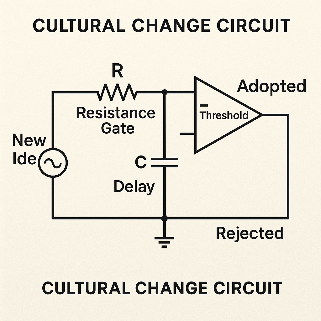
Diagram: Cultural Change Circuit
[New Idea] → [Resistance Gate]
                ↓
        → [Delay Capacitor] → [Output = Adopted or Rejected]
Explanation:
- New Idea (source): A periodic or novel concept enters via the voltage source.
- R (Resistance Gate): Represents cultural resistance or inertia slowing adoption.
- C (Delay): Models generational delay, ideas charge the capacitor over time.
- Comparator (Threshold): Decides if voltage (idea strength) crosses adoption threshold.
- High → Adopted: Idea is integrated into culture.
- Low → Rejected: Idea fades without acceptance.
This RC-filter plus comparator shows culture as a slow-change circuit where memory and resistance define the pace of evolution.
Cultural wisdom isn’t just story, it’s encoded circuitry that survived the noise.
Applications
- Ritual design for healing, onboarding, grief, celebration
- UX design as ritual logic sequence
- Educational symbols that embed logic
- Cultural preservation tools as EEPROM emulators
- Tuning social change by adjusting resistance and feedback
Insight
Culture is not fluff, it is deep infrastructure. Rituals are not quaint, they are circuit-level programming languages for emotional and social behavior.
When you build with symbols and sequence, you’re not manipulating belief. You’re engaging with the operating system of the human collective.
Part 14: Economics as Electric Flow – Modeling Money, Work, Scarcity, and Value
“Money is voltage. Work is current. Scarcity is resistance. Economics isn’t abstract, it’s circuitry. And once you draw it, you can debug it.”
Welcome to the economy, reimagined not as spreadsheets and jargon, but as flow, load, impedance, and signal. Here, we diagram money and value systems using electrical logic. This opens a new window into:
- Inequality
- Market collapse
- Debt cycles
- Resource allocation
When seen as systems of energy flow, economic behavior becomes something you can design, repair, and innovate.
1. Money = Voltage (Potential Energy)
Money isn’t the flow itself, it’s the potential to cause flow. Just like voltage:
- Higher money = higher potential to act
- No money = system stagnation
Diagram: Basic Economic Load

[Money Source] ──▶ [Load: Labor / Goods] ──▶ [Output Value]
Explanation:
- Money Source (voltage): Provides economic potential energy.
- Load: Labor/Goods (resistor): Represents work or products that convert money into value.
- Output Value (current): The realized economic output, goods produced or services rendered.
Without voltage (money), no current flows. The circuit stays inactive, mirroring how lack of funds halts economic activity and there is no incentive signal to activate the circuit.
2. Work = Current (Flow of Labor or Effort)
Work is the actual flow of energy through the system. It turns potential into real-world output.
- Work requires effort (amps)
- Overwork = overload
- No flow = no production
Diagram: Effort Circuit
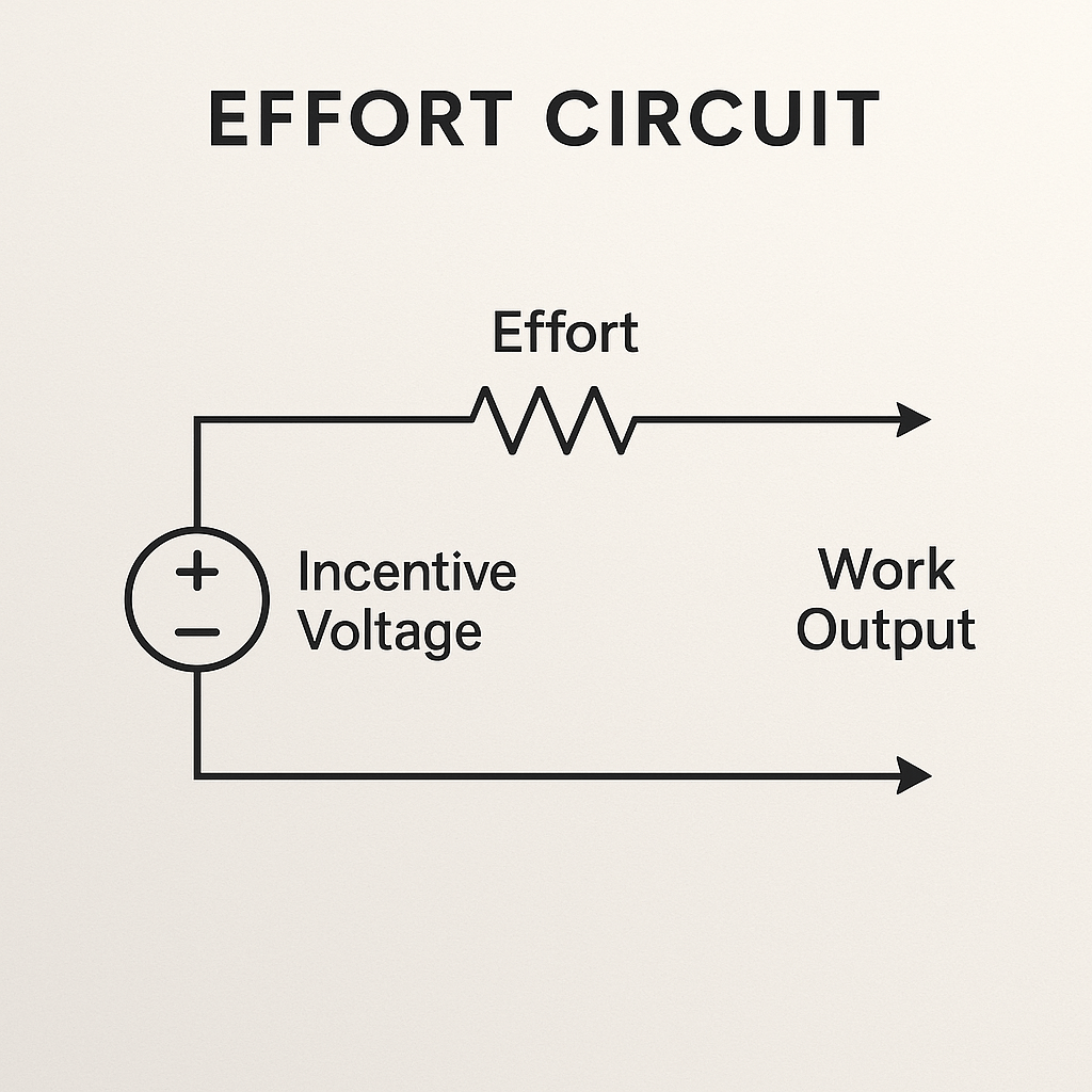
[Incentive Voltage] ──▶ [Resistor (Effort)] ──▶ [Work Output]
Explanation:
- Incentive Voltage (voltage source): Drives the effort circuit.
- Effort (resistor): Represents labor or difficulty, lower resistance increases current for a given voltage.
- Work Output (current arrows): The actual flow of work produced.
The resistor represents difficulty. Less resistance = more output per volt.
3. Scarcity = Resistance
Scarcity isn’t just absence, it’s impedance to flow:
- High resistance = goods are rare or expensive
- Low resistance = goods are abundant or cheap
Diagram: Scarcity Barrier
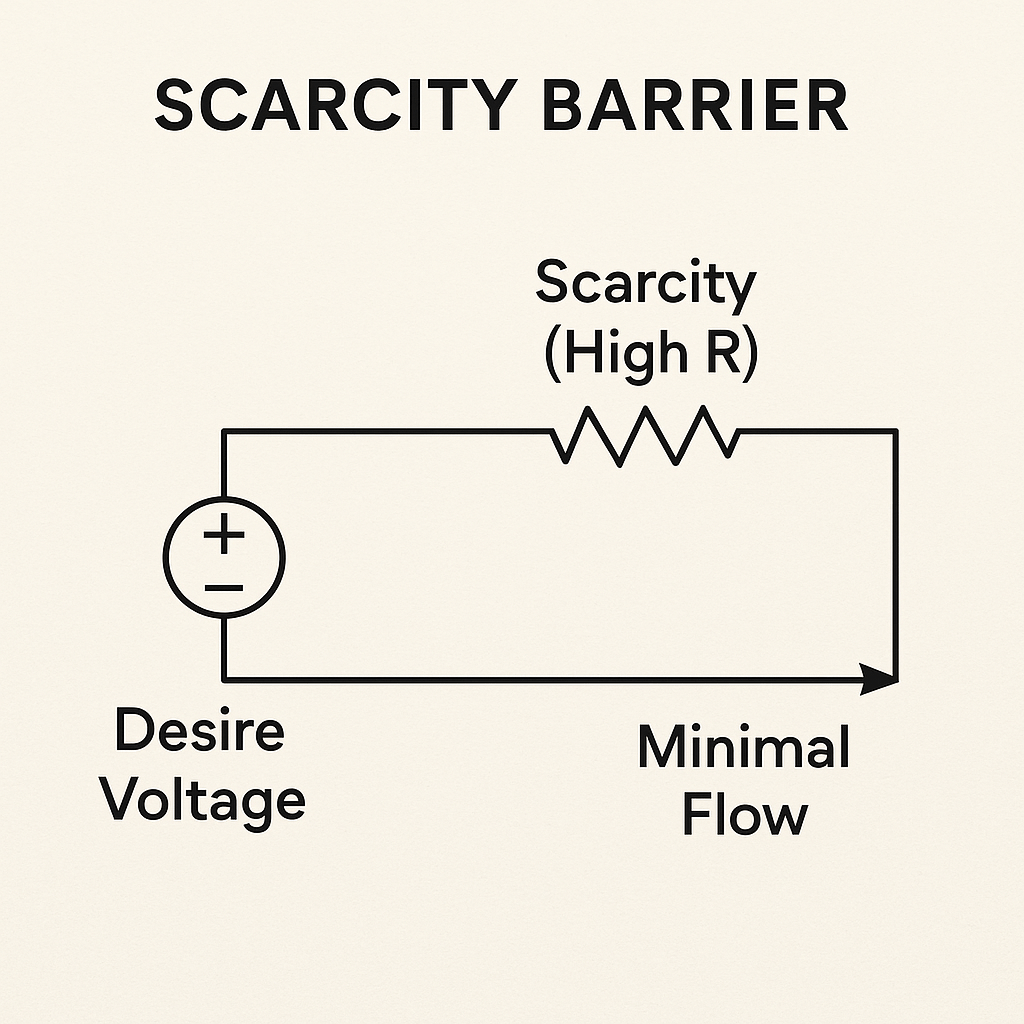
[Desire Voltage] ──▶ [High Resistor: Scarcity] ──▶ [Minimal Flow]
Explanation:
- Desire Voltage (Source): The driving potential, economic demand or incentive.
- Scarcity (High R): A large resistor reducing current, models limited supply or high cost.
- Minimal Flow (Arrow): The resulting small current flow, low transactions or production.
By placing the resistor directly in series and containing all elements within the frame, this schematic accurately depicts how scarcity translates potential into friction and constrains flow.
Scarcity transforms money into friction.
4. Markets = Signal Routers + Feedback Gates
Markets route energy (money) to where demand signals are strongest. They also:
- Amplify popular products
- Suppress weak demand
- Self-correct via feedback
Diagram: Market Feedback Loop

[Consumer Demand] ──▶ [Signal Router] ──▶ [Price Amplifier]
                              ↑
                     ↻ [Feedback from Supply/Price Shift]
Explanation:
- Consumer Demand → Signal Router → Price Amplifier: The core forward path of the market process.
- Supply/Price Feedback: Gathered at a feedback block that splits to both router and demand, closing the loop.
Markets self-organize, but can also destabilize without regulation or accurate feedback.
5. Debt = Time-Shifted Voltage with Feedback Risk
Debt is borrowed voltage, future energy pulled into the present.
- Amplifies flow now
- Creates feedback load later
- If repayment exceeds income: collapse
Diagram: Debt Circuit

[Future Potential] → [Amplifier] → [Current Output]
                                ↓
                       ↻ Repayment Feedback → Resistance Load
Explanation:
- Future Potential (voltage source): Represents borrowed energy, money pulled from the future.
- Amplifier: Boosts present cash flow, enabling immediate output beyond current capacity.
- Current Output → Resistance Load: The amplified energy drives spending or investment.
- Repayment Feedback Loop: The load’s output cycles back through a controlled feedback path, debt repayment, which imposes a future burden.
- Risk of Collapse: If repayment demand (feedback) exceeds ongoing potential (income), the circuit saturates and fails, modeling insolvency.
Debt acts as a time-shifted voltage source: powerful when managed, but requiring controlled feedback to prevent collapse.
Debt is a tool for boosting present capability but must be managed to avoid feedback-induced failure.
Applications
- Design economic simulations with real-world emotional logic
- Explain inflation as feedback loop gain
- Build game economies with energy-based logic
- Reimagine systems of distribution, taxation, incentive
- Model inequality as circuit topology failure
Insight
Economics isn’t separate from emotion, it’s the nervous system of a civilization. And money isn’t evil or sacred, it’s just a voltage line. Once you see the wires, you can trace the shortages, reroute the overloads, and design a world that actually flows.
Part 15: Wealth Distribution, Rent, and Extraction – Skimmers, Gates, and Value Loops
“Not all flow is fair. Some nodes skim more than they contribute. Some gates open only one way. Wealth doesn’t just accumulate, it’s routed. And those routes can be drawn.”
We saw how economics mirrors electricity: money as voltage, work as current, scarcity as resistance. Now, we trace how wealth moves, stalls, and concentrates, or leaks entirely, using circuit metaphors.
Inequality isn’t just a statistic, it’s a circuit configuration. By visualizing skimming, rent-seeking, and extraction through diagrams, we can finally see the mechanics of injustice, and maybe start rewiring the system.
1. Wealth Accumulation = Node with Capacitor + Low Output Resistance
Wealth is stored energy. If a node receives flow but gives little back, it accumulates charge.
Diagram: Accumulator Node

[Income Flow] ──▶ [Node] ──▶ [Capacitor: Wealth Storage]
                             ↓
                     Low Output = Retained Wealth
Explanation:
- Income Flow enters the node via a unidirectional path, suggesting controlled intake of resources.
- The Node represents an economic agent receiving income.
- A Capacitor stores this income as Wealth, modeling the accumulation of unused energy.
- A Resistor in series with the capacitor represents low output resistance, allowing only slow or limited energy discharge.
- The combination creates a condition where inflow > outflow, resulting in increasing stored charge (wealth).
- Wealth accumulates fastest when output resistance is low and the node retains more than it distributes.
Wealth, like charge, builds fastest where resistance is low and output is limited.
2. Rent-Seeking = Skimmer Circuit
Rent-seeking extracts value without producing flow, a parallel skim from the current of others.
Diagram: Rent Skimmer

[Labor Flow] ──▶ [Value Path] ──▶ [Output]
                          ↓
                   → [Skimmer Branch] → [Landlord / License / Toll]
Explanation:
- Labor Flow represents productive energy moving into the system.
- The Value Path is the legitimate, functional channel of output, what workers or producers generate.
- A Skimmer Branch diverts part of this current via a parallel path.
- The Resistor on the skimmer path limits the skim amount but ensures continuous passive draw.
- This branch leads to Landlord / License / Toll, representing entities that extract value without producing.
- The main output remains functional, but part of the energy is lost to overhead, designed into the circuit, not accidental.
- This models rent-seeking as a structural parasitic load, legal, continuous, and built-in.
This isn’t theft, it’s design. The circuit diverts energy without adding function.
3. Extraction Loops = Recursive Drain Circuits
In extraction economies:
- Resources (labor, minerals, money) are funneled out of one region
- Never reinvested
- Cause systemic collapse
Diagram: Extraction Feedback
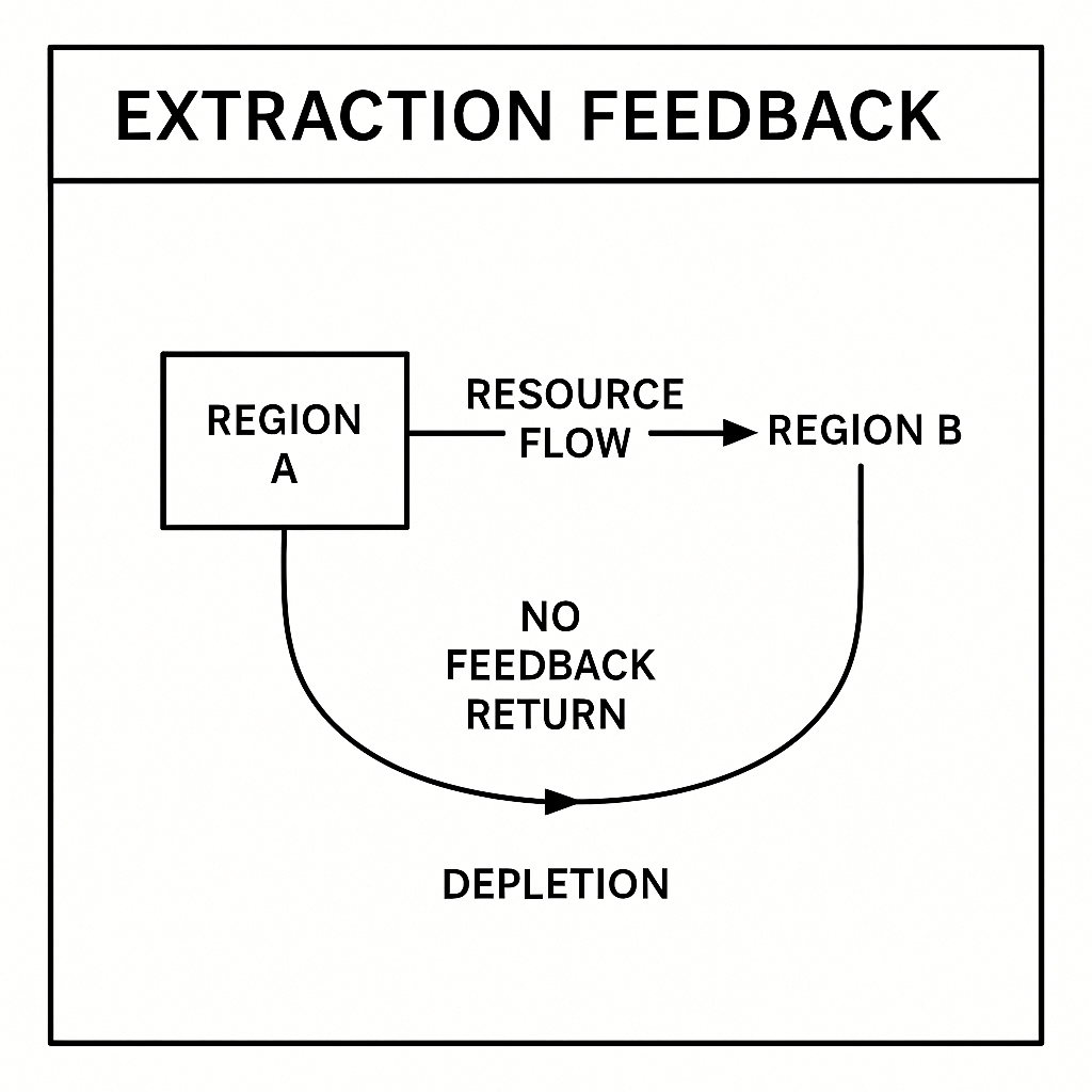
[Region A] → [Resource Flow] → [Region B]
                  ↓
            ↺ No Feedback Return → Depletion
Explanation:
- Region A generates or holds natural, financial, or human capital.
- Resource Flow channels these assets to Region B, representing central authority, capital holders, or foreign powers.
- The system lacks a feedback return, no reinvestment or regenerative current loop.
- Over time, Region A depletes, like a battery drained with no charger.
- This models extraction economies, where systemic design ensures unidirectional flow and eventual collapse of the source.
- The loop is not incomplete by accident, it is a closed extraction path by design.
Like a battery with no recharge line, the source dies.
4. Gatekeeping = Signal Access Restriction
Some systems are designed with high-threshold gates:
- Education gates
- Licensing gates
- Social capital gates
These block entry unless high voltage (resources) is applied.
Diagram: Gatekeeping Filter

[Signal] ──▶ [Comparator: Must > Threshold] ──▶ [Access]
       ↓
   Blocked if Input Too Low
Explanation:
- Signal represents an individual’s attempt to gain access (education, job, membership).
- The Comparator checks whether the signal voltage exceeds a preset Threshold.
- If the signal is above threshold, access is granted, symbolizing qualified entry.
- If the signal is below threshold, it is routed to a blocked path, denying access.
- This models gatekeeping structures, where only those with high input (resources, credentials, capital) can pass.
This perpetuates stratification, not because people lack value, but because they lack input voltage.
5. Hyperaccumulation = Positive Feedback Without Clamp
When wealth generates more wealth (interest, capital gains) without reinvestment, the circuit forms a runaway feedback loop.
Diagram: Wealth Spiral

[Wealth Node] → [Investment Return] → [More Wealth]
                       ↑                  ↓
                  ↺ Feedback Without Redistribution Clamp
Explanation:
- The Wealth Node represents initial capital or assets.
- Investment Return feeds directly back into the same node without external drain.
- This creates a positive feedback loop, where returns amplify the original input.
- The absence of a clamp (no resistive loss, redistribution, or regulation) causes unchecked amplification.
- More Wealth compounds, reinforcing the loop and escalating imbalance.
- Functionally identical to thermal runaway in electronics, an unstable, accelerating loop that destabilizes the system.
This destabilizes systems the same way a thermal runaway fries a transistor.
6. What Healthy Wealth Flow Looks Like
A fair system includes:
- Capacitor limits (wealth tax, reinvestment incentives)
- Balanced feedback (recycling wealth into infrastructure)
- Clamps on extraction (regulatory return paths)
- Low-threshold access gates (education, opportunity)
Diagram: Equitable Wealth Flow
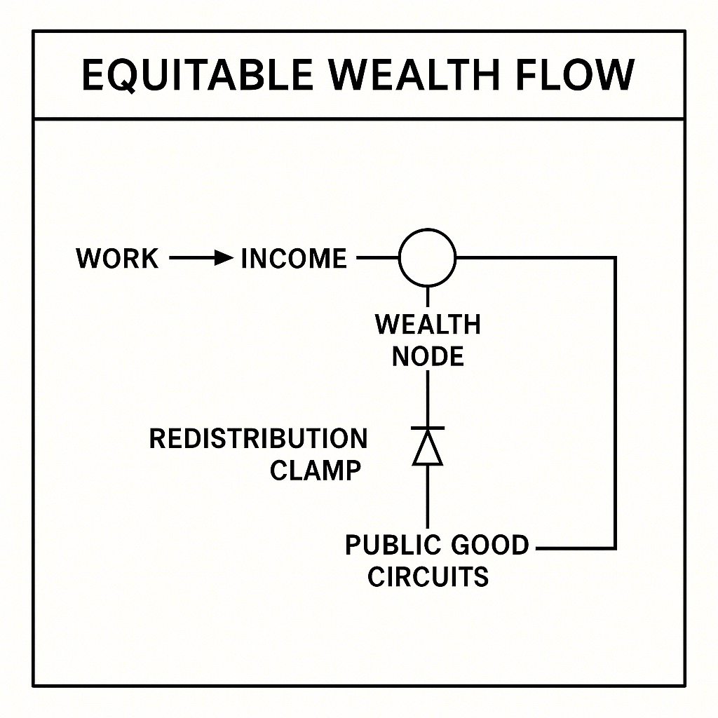
[Work] → [Income] → [Wealth Node]
          ↓        ↘
      [Redistribution Clamp] → [Public Good Circuits]
Explanation:
- Work drives Income, representing earned value through effort or productivity.
- Income flows into a Wealth Node, where resources are collected.
- A Redistribution Clamp (shown as a Zener or clamp diode) diverts excess charge into parallel paths.
- This ensures overflow is routed into Public Good Circuits, education, infrastructure, healthcare.
- The clamp stabilizes the system by limiting runaway accumulation, maintaining flow integrity.
- Not all wealth is redirected, just enough to preserve systemic balance, ensuring reciprocity and reinvestment.
Stability is not about “equality”, it’s about flow integrity.
Insight
Wealth is not evil. Accumulation is not failure.
But unchecked skimming, gatekeeping, and extraction are not flaws, they are electrical faults. And any good engineer knows what to do with a faulty circuit: trace it, test it, and redesign it for balance.
Part 16: Debt, Interest, and Collapse – Time-Based Inversion and Systemic Overload
“Debt is not evil. But it is dangerous. It’s a voltage you borrow from the future. If you draw too much, too fast, without discharge paths, you collapse. Not just financially, but systemically.”
We diagrammed wealth flows, rent-seeking, and accumulation using circuit models. Now we examine a subtler, more insidious force: debt.
Debt is a brilliant mechanism, one of the few that lets systems flex over time. But it’s also a temporal inversion gate: you draw energy forward, then pay it back with feedback, and interest.
When properly designed, it accelerates growth. When left unchecked, it becomes recursive amplification that burns out the system.
1. Debt = Future Voltage Activated Now
Debt is a delayed-signal amplifier:
- You receive a boost of voltage now
- But must later provide equal or greater return
Diagram: Debt Logic

[Borrow Request] → [Amplifier] → [Current Activation]
                           ↓
               ↺ [Feedback: Future Repayment Path]
Explanation:
- Borrow Request feeds into the non-inverting (+) input of the op-amp, initiating demand.
- The Amplifier boosts the signal, creating Current Activation, access to future energy now.
- A Feedback Loop connects the output to the inverting (−) input, labeled Future Repayment.
- This feedback balances the circuit: repayment signal must match the original amplification demand.
- The system represents a classic closed-loop control, stable only if the future can compensate the present.
- Without proper feedback, the amplifier saturates, mirroring default, inflation, or collapse.
Debt isn’t negative. It’s signal shift, borrowing future current.
2. Interest = Feedback Multiplier
Interest is a form of signal gain:
- The longer the delay, the more signal must be returned
- This creates exponential curves
Diagram: Interest Feedback Loop

[Loaned Voltage] → [Output Flow]
                         ↓
         ↺ Feedback Loop With Gain > 1
Explanation:
- A voltage source labeled Loaned Voltage supplies the initial signal, representing borrowed capital.
- This feeds into the non-inverting input (+) of an operational amplifier, where the output is amplified.
- The Output Flow represents the loan disbursement or economic activity enabled by the borrowed funds.
- A feedback path connects the output back to the inverting input (−).
- The loop is configured with gain > 1, meaning each cycle increases the total output obligation, this models interest accumulation.
- Over time, this feedback causes exponential amplification, paralleling debt growth from compound interest.
- Without damping or redistribution, the system risks instability or collapse from overload.
Unchecked, interest leads to debt spirals, especially when the input can’t sustain the rising output.
3. Default = Threshold Collapse Event
When the system cannot meet the feedback demand, the circuit hits a fault threshold.
- No repayment → signal interruption
- Accumulated interest becomes load rather than flow
- Output halts
Diagram: Default Trigger

[Repayment Signal] < [Comparator Threshold]
             ↓
      → [Breaker] → Output = 0
Explanation:
- The Repayment Signal enters a Comparator, which checks if the input meets the required Threshold.
- If the repayment falls below the threshold, the comparator output changes state.
- This triggers a breaker switch (normally closed), which opens the circuit.
- The output path is now interrupted, resulting in Output = 0, representing credit cutoff or default.
- The node is effectively disconnected from the system, unable to contribute or receive.
- Interest obligations become an unmanageable load, not a flow, leading to circuit fracture or isolation.
The node drops out of the system. Credit disappears. The circuit fractures.
4. Compound Debt = Recursive Exponential Oscillator
If interest is added to principal, and compounded regularly, you create:
- An oscillating output
- Where each loop feeds the next
- Leading to system instability
Diagram: Compounding Circuit
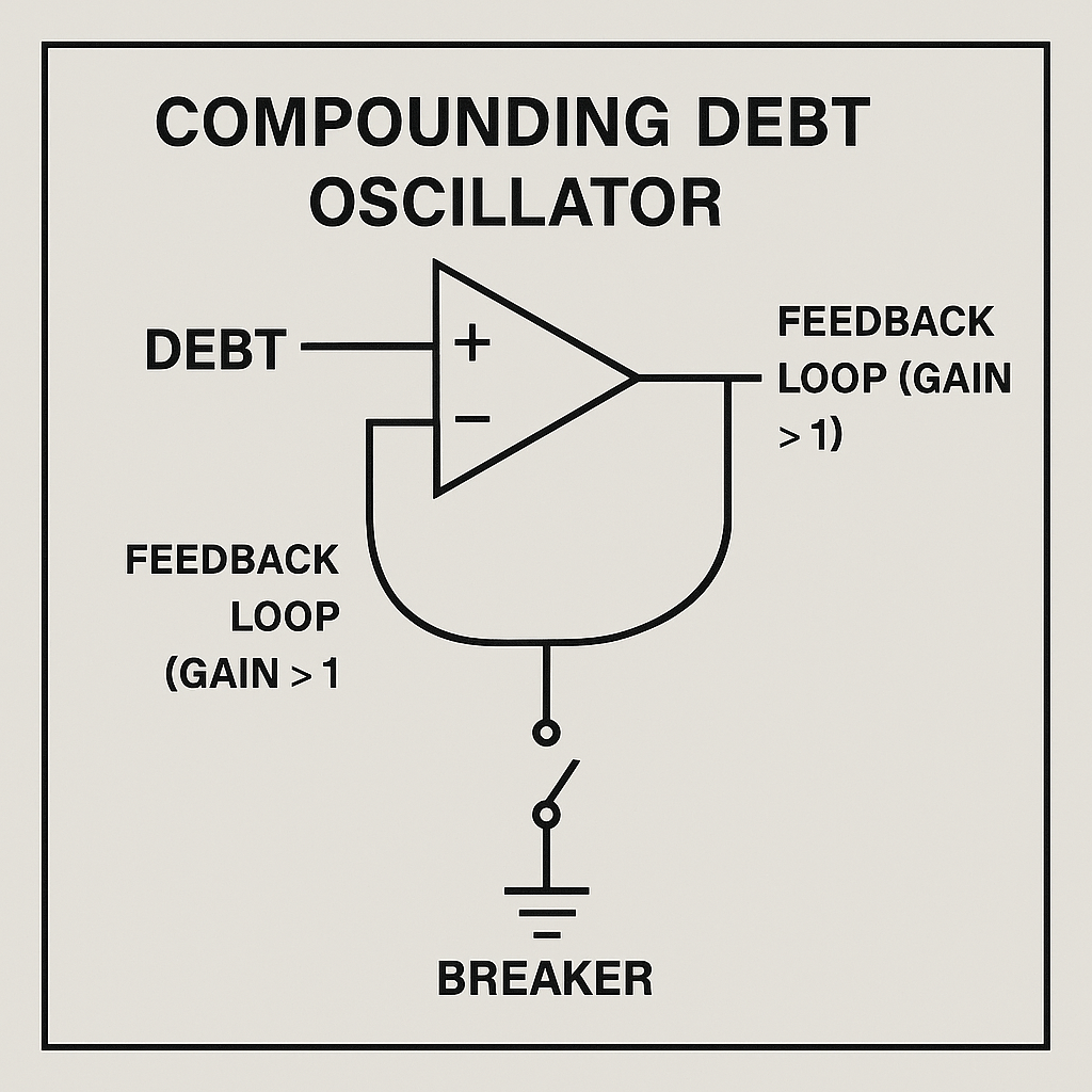
[Debt] → [Amplifier] → [Next Debt Level]
               ↑               ↓
            ↻ [Loop Without Clamp]
Explanation:
- Debt enters the non-inverting (+) input of the amplifier, representing principal plus interest.
- The amplifier’s output is the Next Debt Level, larger due to compounded gain.
- A feedback loop returns this output to the inverting (–) input without a clamp, modeling unchecked compounding.
- Each cycle amplifies the debt further, causing recursive exponential growth.
- A Breaker in the output path shorts the signal to ground when triggered, forcing Output = 0, symbolizing default.
- Without intervention, this positive-feedback design will overload the circuit (electronic meltdown) or destroy the borrower (financial ruin).
In physics, this would melt the component. In economics, it destroys the borrower.
5. Healthy Debt Circuits = Timing, Clamps, and Reset
A well-structured debt system includes:
- Timers (grace periods)
- Voltage clamps (interest caps)
- Reset gates (bankruptcy, debt forgiveness)
- Redistribution circuits (preventing wealth sinkholes)
Diagram: Sustainable Credit Circuit

[Loan] → [Time Delay] → [Output Work]
           ↓
     ↺ Feedback → [Clamp + Reset Conditions]
Explanation:
- Loan enters the amplifier (A), representing funded credit extended to borrowers.
- A Time Delay (RC network) provides a grace period before repayment begins, modeled by the connection from amplifier’s output to delay components.
- Output Work is the productive activity enabled by the loan, this is the main signal path.
- A Clamp (Zener diode + resistor) limits maximum interest, ensuring rates cannot exceed a safe threshold.
- A Reset Conditions gate (switch) allows debt forgiveness or bankruptcy, clearing accumulated obligations when triggered.
- The feedback loop integrates clamp and reset, routing surplus or overdue signals back for regulation.
- Redistribution circuits (implied by the clamp network) prevent wealth sinkholes by redirecting excess into public or community infrastructure.
- This design enforces engineering integrity: controlled timing, capped amplification, and reset mechanisms maintain system stability.
This isn’t utopia, it’s engineering integrity.
Applications
- Redesign personal finance systems using feedback logic
- Build simulations where interest changes over time
- Model national debt as signal flow and thermal load
- Reframe bankruptcy as a reset latch, not failure
- Construct regenerative economic tools with built-in capacitor bleed
Insight
Debt is signal manipulation across time.
Interest is gain without context.
Collapse is logic overflow.
If we want stable futures, we must engineer economic timing circuits carefully.
Part 17: Institutions, Law, and Governance Logic – Constitutions, Override Switches, and Power Regulators
“A government is not an idea. It’s a control system. It routes authority, processes demands, clamps conflict, and regulates power. And like any circuit, if the gates fail or the feedback loops invert, it crashes.”
We’ve diagrammed emotional loops, relational dynamics, economics, and debt. Now we move into the political body, the system that holds them all.
Governance isn’t mystery or metaphor. It’s distributed logic across nodes, with defined authority paths, reset circuits, and safety fuses. It can be designed like a machine, or fail like one.
1. Institutions = Modular Logic Boards
Institutions (courts, parliaments, agencies) are modular systems:
- Each has input types (cases, laws, complaints)
- Logic gates (rules, precedence, budget)
- Outputs (decisions, actions, penalties)
Diagram: Institutional Module
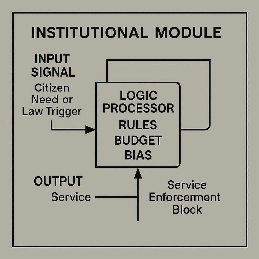
[Input Signal: Citizen Need or Law Trigger]
          ↓
     → [Logic Processor: Rules + Budget + Bias]
          ↓
     → [Output: Service / Enforcement / Block]
Explanation:
- Input Signal represents Citizen Need or Law Trigger entering the institution.
- The Logic Processor block applies Rules, Budget constraints, and Bias factors to the input.
- The Output is a decision: Service, Enforcement, or Block.
- A return path from the output back into the logic block indicates inter-institutional interfaces, necessary for coordination.
- Modular design ensures each institution can process specific inputs and produce relevant outputs, maintaining systemic integrity.
Each institution must interface with others, or the system fragments.
2. Constitution = Read-Only Memory (ROM) + Comparator Logic
A constitution is the foundational rule-set, like firmware:
- Guides other circuits
- Sets thresholds for override
- Acts as comparator when branches disagree
Diagram: Constitutional Check

[New Law Signal] → [Comparator]
            ↑           ↓
     [Constitution ROM]   → [Valid / Invalid Output]
Explanation:
- Law Source (Citizen Petition/Bill Draft) provides the New Law Signal, the proposed rule entering the system.
- The Comparator evaluates this signal against the Constitution ROM, which holds the immutable rule-set.
- If the New Law Signal meets or exceeds the ROM reference, the comparator emits Valid; otherwise, it outputs Invalid.
- A Reset Conditions gate allows for constitutional amendments or judicial review, clearing or updating the comparator state.
- The ROM represents foundational firmware, any tampering undermines system coherence.
- This circuit ensures every law conforms to the core constitutional thresholds before taking effect.
Tamper with ROM? The whole system may become incoherent.
3. Checks and Balances = Reciprocal Clamping Loops
Healthy governance uses feedback clamping:
- Executive clamps legislative excess
- Judiciary filters legislative intent
- Legislature checks executive impulse
Diagram: Power Balance Loop

[Branch A] ⇄ [Branch B] ⇄ [Branch C]
        ↻ Mutual Feedback + Threshold Logic
Explanation:
- Executive clamps legislative excess: Resistor from Executive output to Legislature non-inverting input.
- Legislature checks executive impulse: Resistor + diode from Legislature output to Executive inverting input.
- Judiciary filters legislative intent: Resistor + diode from Judiciary output to Legislature non-inverting input.
- Direct feedback lines interconnect Legislature → Judiciary → Executive → Legislature, enforcing Mutual Feedback + Threshold Logic.
Removing any clamp resistor or diode breaks that feedback path, allowing one branch to dominate or go rogue.
4. Override Switches = Emergency Powers
In crisis, certain systems bypass normal rules:
- Martial law
- Executive orders
- Emergency spending
Useful only if bounded.
Diagram: Override Circuit
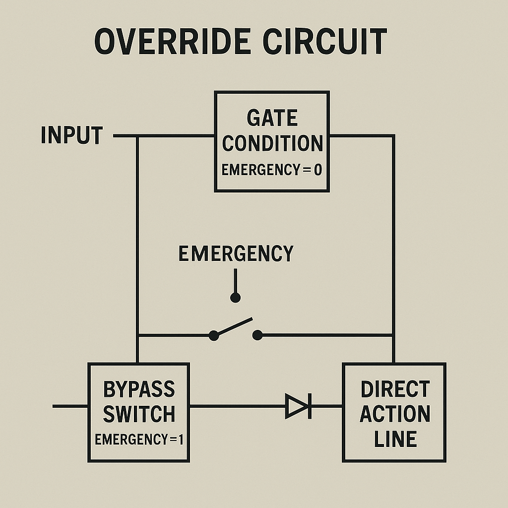
[Normal Path] → [Gate Condition: Emergency = 0] → [Standard Output]
         ↘
    If Emergency = 1 → [Bypass Switch] → [Direct Action Line]
Explanation:
- Input branches upward to the Gate Condition block, which closes the path when Emergency = 0, allowing flow to Standard Output.
- Input also branches downward to the Bypass Switch, which closes when Emergency = 1, routing signals to the Direct Action Line.
- A central Emergency control toggles the gate and bypass switch states.
Without integrated timers, clamps, or reset conditions, the bypass path can become the default, undermining normal operation.
5. Corruption = Feedback Inversion + Skimming Circuits
Corruption flips governance feedback:
- Officials skim resources (parallel extraction loop)
- Rules serve power, not people
Diagram: Corruption Path

[Public Signal] → [Official Node]
          ↓         ↘
    [Skimmer Branch]   → [Self-Gain Output]
          ↓
   ↺ Feedback Alters Logic Behavior
Explanation:
- Public Signal enters the non-inverting (+) input of the Official Node (op-amp).
- The Official Node outputs Self-Gain Output, representing personal enrichment.
- A Skimmer Branch taps the output through a resistor to ground, depicting resource diversion.
- A diode in the skimmer path directs the skimmed signal into the inverting (–) input, completing the feedback inversion loop.
- This inverted feedback reinforces corrupt behavior, flipping governance logic so rules serve self-gain rather than public good.
Corruption is not “bad people”, it’s malfunctioning design logic.
Advanced Design: Governance as Dynamic Logic Network
A resilient government:
- Uses EEPROM rules (persistent, modifiable only under consensus)
- Implements feedback buffers (media, protest, courts)
- Includes manual reset paths (elections, impeachment)
- Regulates input flow to prevent overload (filibusters, quorums)
It’s not about ideology, it’s about control architecture.
Applications
- Build models of different political systems (monarchy = locked gate; democracy = multi-voter logic)
- Simulate institutional collapse (removal of buffers or ROM corruption)
- Teach civics through interactive circuits
- Develop governance sandboxes
- Re-design organizations using circuit templates (departments = modules)
Insight
Governments fail when their logic breaks, not just their leaders. Constitutions are not holy, they are circuit blueprints. Law is not justice, it is signal logic. And power must be regulated, or it will always burn through the board.
Part 18: Corruption, Collapse, and Revolt – Feedback Hijacks and System Failures
“Societies don’t fall apart from sudden chaos, they collapse from broken circuits. Overloaded nodes, inverted feedback, locked gates, and runaway amplifiers. Collapse is not random. It is system failure, and it can be drawn.”
We’ve built the architecture of emotions, relationships, economies, and governance. Now we turn to failure modes, not as metaphors, but as mechanical events in logic systems.
Corruption is a feedback hijack.
Collapse is a sustained overload without reset.
Revolt is an emergent output, unrecognized, unbuffered, and powerful.
Let’s diagram how systems break, and how these breakdowns follow exacting patterns.
1. Collapse = Amplified Feedback With No Clamps
When corruption, resource loss, or internal conflict intensify without a brake:
- Load exceeds capacity
- Feedback accelerates
- Gates break
This is runaway recursion.
Diagram: Collapse Feedback
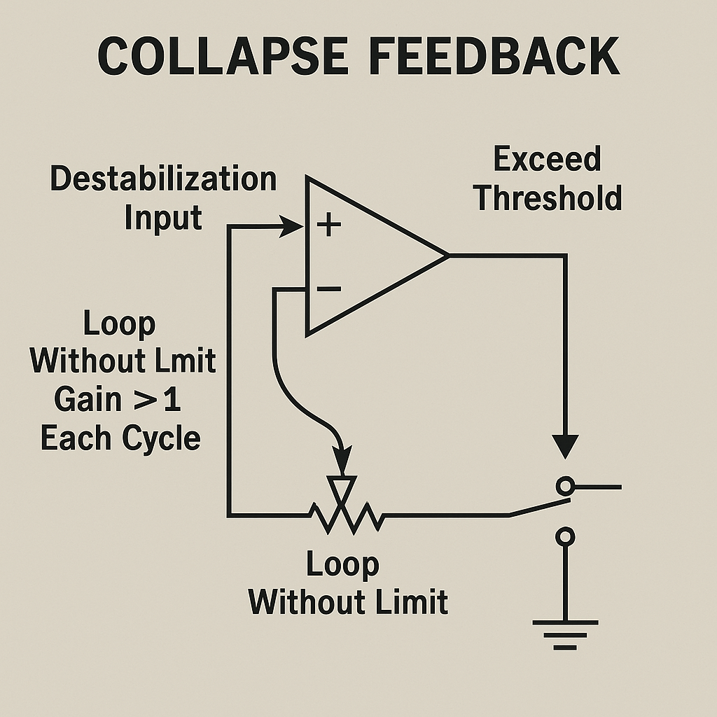
[Destabilization Input] → [Loop Without Limit]
                ↺ Gain > 1 Each Cycle
                 ↓
       → Exceed Threshold → Total System Halt
Explanation:
- Destabilization Input enters the non-inverting (+) input of the amplifier, representing initial disturbance.
- A Loop Without Limit (direct feedback to the inverting – input) produces Gain > 1 Each Cycle, accelerating output without damping.
- The amplifier’s Output feeds into a Comparator labeled Exceed Threshold, monitoring when the signal surpasses safe bounds.
- Once threshold is reached, the Breaker opens the circuit, leading to Total System Halt.
- Collapse occurs not from a single shock but from the absence of clamps or damping, allowing runaway recursion to overwhelm the system.
Collapse isn’t the fall. It’s the failure to dampen acceleration.
2. Inflexibility = Frozen State With No Reset Path
Institutions collapse faster when they can’t adapt:
- No override gate
- No update mechanism
- No dynamic reconfiguration
These become brittle, and eventually shatter under minimal pressure.
Diagram: Frozen Logic

[Input Shift] → [Inflexible Node]
           ↓
      → Logic Error → No Output
         ↘
    [Manual Reset Blocked]
Explanation:
- Input Shift enters the Inflexible Node (comparator), representing changing conditions the system cannot handle.
- The Inflexible Node outputs a Logic Error, indicating failure to process the shifted input.
- A Manual Reset path is present but shown with an open switch, blocking any reset or override mechanism.
- Without a feedback loop, timers, or dynamic reconfiguration, the system remains frozen, any input shift leads to permanent error.
- This brittle design turns outdated rules into death traps, collapsing under minimal pressure.
This is how outdated rules become death traps.
3. Revolt = Emergent Discharge Through Unbuffered Paths
Revolt isn’t chaos, it’s a natural response to:
- Persistent overload
- Blocked feedback
- Inaccessible reset logic
It is signal re-routing outside authorized circuits.
Diagram: Revolt Pulse

[Suppressed Feedback] → [Charge Accumulator]
                  ↓
           ↘ [Bypass Line] → [Revolt Output] → System Reconfiguration Attempt
Explanation:
- Suppressed Feedback enters the node and charges the Charge Accumulator (capacitor) until it reaches a sufficient level.
- The Bypass Diode activates when the accumulator’s voltage exceeds its forward threshold, creating the Revolt Output pulse.
- The Revolt Output is routed into the System Reconfiguration Attempt block, representing efforts to change or rewire the existing structure.
- If the system cannot integrate this external reconfiguration signal, lacking reset or adaptive logic, the revolt pulse overloads the system and leads to burnout.
If the system cannot integrate revolt, it will burn out.
4. Systemic Failure = Loss of Signal Integrity Across Network
Collapse is complete when:
- Nodes stop trusting inputs
- Signals no longer match outcomes
- Feedback is no longer interpreted
The system becomes white noise.
Diagram: Signal Dissolution

[Multiple Node Inputs] → [Broken Routing Matrix]
           ↓
        → Incoherent Output → Shutdown or External Override Required
Explanation:
- Node Input 1/2/3 are separate signal lines intended to feed into the system.
- The Broken Routing Matrix (dashed block) represents failed interconnections, only one path remains intact.
- Outputs from the matrix split:
- One line goes to the Incoherent Output, signifying mismatched or garbled signals.
- Another line leads through an open switch to Shutdown / External Override, representing the need for manual intervention.
- Loss of routing integrity causes nodes to distrust inputs, producing white-noise outcomes unless an external override restores order.
Societies don’t die. They hang, like unresponsive software.
Applications
- Build political simulations of failure using real input conditions
- Visualize revolutions as circuit-based reboots
- Train reformers to spot feedback corruption
- Design systems with redundant resets, buffered pathways, and multi-gate integration
Insight
Collapse is not fate, it is design failure.
Revolt is not madness, it is signal overflow.
Corruption is not evil, it is path divergence.
You cannot fix a broken system with words alone. You need to trace the wires, test the logic, and design a circuit that learns.
Part 19: Market Behavior and Monetary Psychology – Speculation, Inflation, and Value Loops
“Markets are not rational, they are reactive. They don’t move with logic alone, but with emotion: fear, greed, trust, and momentum. That’s not metaphor. It’s circuitry.”
In the last section, we mapped collapse and revolt as system-wide logic failures. Now we shift to the emotional circuits within markets, where speculation amplifies signals, inflation distorts current, and value perception becomes an unstable loop.
Markets don’t just trade goods. They transmit belief, process emotion, and generate mass behavior in real-time. Let’s diagram how.
1. Speculation = Delayed Reward Feedback With Gain
Speculation occurs when people act not on current value, but anticipated future signal.
- Signal is based on expectation
- Gain is amplified by belief, not fundamentals
- Feedback loop intensifies
Diagram: Speculative Loop
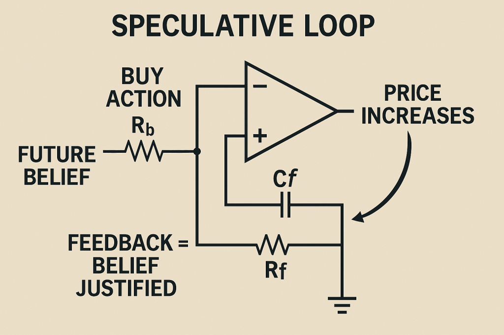
[Future Belief] → [Buy Action] → [Price Increases]
                            ↑            ↓
               ↺ Feedback = Belief Justified
Explanation:
- Future Belief passes through resistor Rb into the Buy Action node, which feeds the non-inverting (+) input of the op-amp.
- The op-amp output, labeled Price Increases, reflects market price driven by buying pressure.
- A feedback network from the output to the inverting (–) input consists of a capacitor Cf in series with a resistor Rf to ground.
- Cf charges when the output rises, integrating the price signal and creating a delayed feedback effect.
- A curved arrow from Price Increases back to Future Belief signifies Feedback = Belief Justified, reinforcing speculative behavior.
- This loop detaches price from intrinsic value, without clamping, it escalates until the circuit (market) eventually snaps.
Speculation detaches price from value, the circuit floats until it snaps.
2. Boom-Bust = Oscillating Emotional Amplifier
Booms and busts are not errors, they’re unstable oscillator circuits:
- Confidence grows → demand rises
- Price overshoots → panic sets in
- Value crashes → cycle resets
Diagram: Market Oscillator
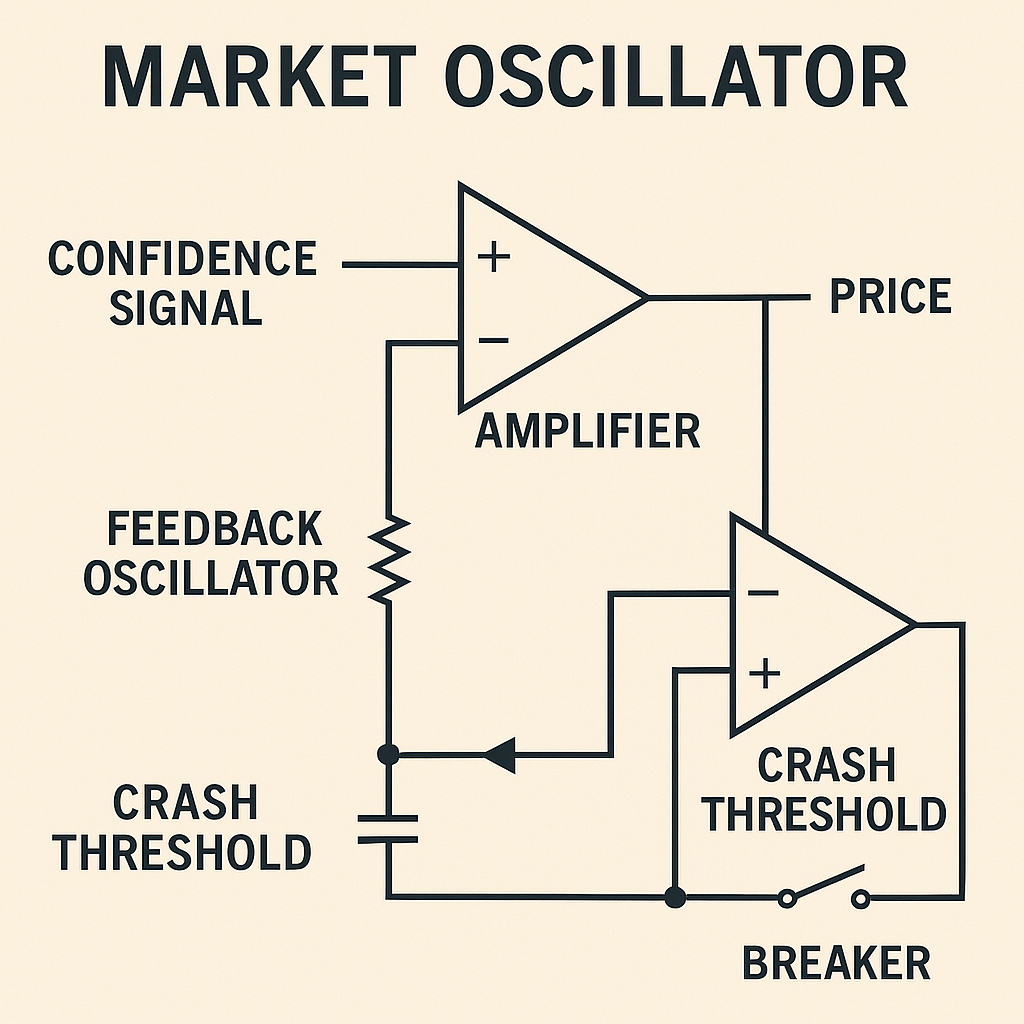
[Confidence Signal] → [Amplifier] → [Price]
                         ↓
                ↻ Feedback Oscillator
                         ↓
                   [Crash Threshold → Reset]
Explanation:
- Confidence Signal enters the non-inverting (+) input of the Amplifier, modeling rising market confidence.
- The amplifier’s Output (Price) feeds into the Feedback Oscillator network (resistor + capacitor), creating an unstable oscillation loop.
- The Crash Threshold comparator monitors the Feedback Oscillator node against a preset reference.
- When price oscillations exceed the Crash Threshold, the comparator closes the Breaker, resetting the feedback node to ground (market crash).
- This loop, amplification, oscillation, threshold trip, reset, produces the classic boom-bust cycle as a mechanical signal oscillator.
This is not psychology or economics, it’s signal mechanics.
3. Inflation = Voltage Saturation Without Output Growth
Inflation occurs when more voltage (money) enters the system without matching output:
- Too many signals chasing the same goods
- Resistance doesn’t increase, but price does
Diagram: Inflation Circuit

[Increased Voltage Supply] → [Same Load]
                         ↓
            → [Output: Higher Price, Not More Goods]
Explanation:
- Increased Voltage Supply (DC source) and a current source in parallel symbolize an expanding money supply injecting additional “voltage” into the economy.
- This node feeds through the Goods Load resistor, representing a fixed quantity of goods or productive capacity that cannot grow with extra money.
- The resistor’s voltage drop becomes the Price Signal, which is sent into the non-inverting (+) input of the operational amplifier.
- The inverting (–) input is tied to a fixed reference (Vref) at ground, setting the baseline price level.
- The op-amp amplifies any excess voltage above Vref, outputting a higher voltage labeled Higher Price, analogous to inflation driving up prices without increasing real output.
- Because the goods load remains unchanged, extra “voltage” only distorts the signal (price), not the actual production of goods, reflecting how inflation raises prices but doesn’t boost real supply.
More energy doesn’t mean more productivity, it means signal distortion.
4. Confidence = Voltage Regulator
Markets rely on stable belief systems. Confidence is not emotion, it’s a voltage regulator:
- Keeps prices within predictable range
- Absorbs shocks
- Prevents runaway feedback
Diagram: Confidence Clamp
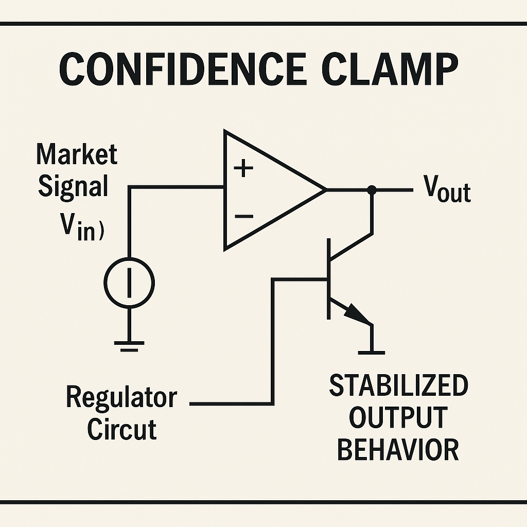
[Market Signal] → [Regulator Circuit]
                      ↓
            [Stabilized Output Behavior]
Explanation:
- Market Signal (Vin) enters a current source representing incoming market fluctuations.
- The Regulator Circuit (op-amp error amplifier) compares Vin at its + input against a stable Vref at its – input (implicit inside the op-amp symbol).
- The op-amp drives the pass transistor, modulating how much of Vin becomes Vout.
- Vout is fed back to the op-amp’s – input, closing the control loop.
- The stabilized output behavior ensures prices stay within predictable bounds, absorbing shocks and preventing runaway feedback in the system.
Lose the regulator? You get panic, or euphoria. Either can break the system.
5. Value = Shared Signal Agreement
Value is not intrinsic. It’s signal consensus:
- What people agree a thing is worth
- Maintained by feedback, memory, and cultural stability
Diagram: Value Loop
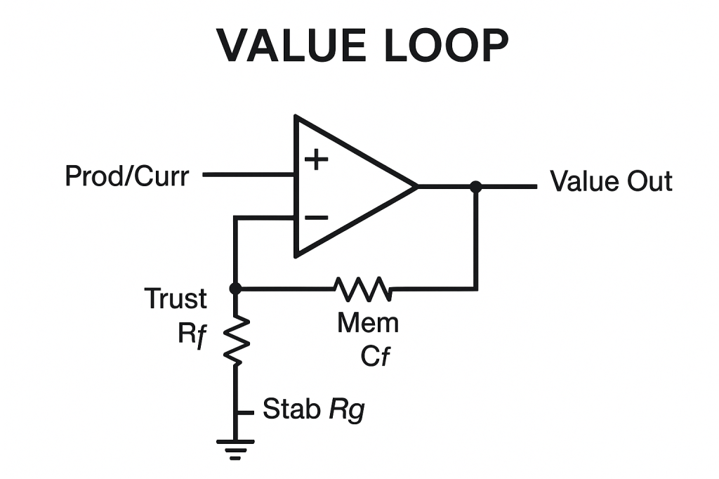
[Signal Input: Product or Currency]
     ↓
 → [Shared Comparator Logic: “What’s It Worth?”]
     ↓
 ↺ [Feedback Loop: Confirmation via Trade and Trust]
Explanation:
- Prod/Curr: Input signal (product or currency)
- Trust Rf: Immediate consensus feedback
- Mem Cf: Stores past confirmations (memory)
- Stab Rg: Grounds reference for stability
- Value Out: Emergent consensus value
Breaking Rf/Cf opens the loop, value collapses.
Break the loop? Value evaporates. Money dies.
Applications
- Simulate financial bubbles as oscillator circuits
- Model speculative assets as logic loops with delayed feedback
- Build emotional finance education tools using schematic diagrams
- Predict crash thresholds based on signal overloads or belief loss
- Re-design markets with signal dampers and output clamps
Insight
Markets are emotional processors. They run on trust, delay, amplification, and decay.
If we treat them like physics, ignoring the signal logic of mass psychology, we lose control.
But if we see their circuit structure, we can regulate with precision. Not through suppression, but feedback design.
Part 20: Governments, Laws, and Constitutions – Logic Systems for Collective Behavior
“Law is not a suggestion, it’s a circuit constraint. A gate, a threshold, a signal limiter. Constitutions are not sacred, they are firmware. Governments are not abstractions, they are control boards.”
We’ve now explored emotion, economy, and collapse through the lens of schematic logic. But perhaps the most underappreciated machine of all is the legal system, the structured logic that governs millions of behavior circuits simultaneously.
We now map how laws, constitutions, and governance bodies operate as cascaded logic controllers, routing inputs (behaviors, disputes, demands) into output conditions (permissions, punishments, protections).
1. Government = Hierarchical Multi-Gate System
Governments route behavior across layers:
- Input: demand, need, proposal, violation
- Logic Gates: policies, regulations, judiciary logic
- Output: permission, denial, taxation, service
Diagram: Governmental Logic Flow
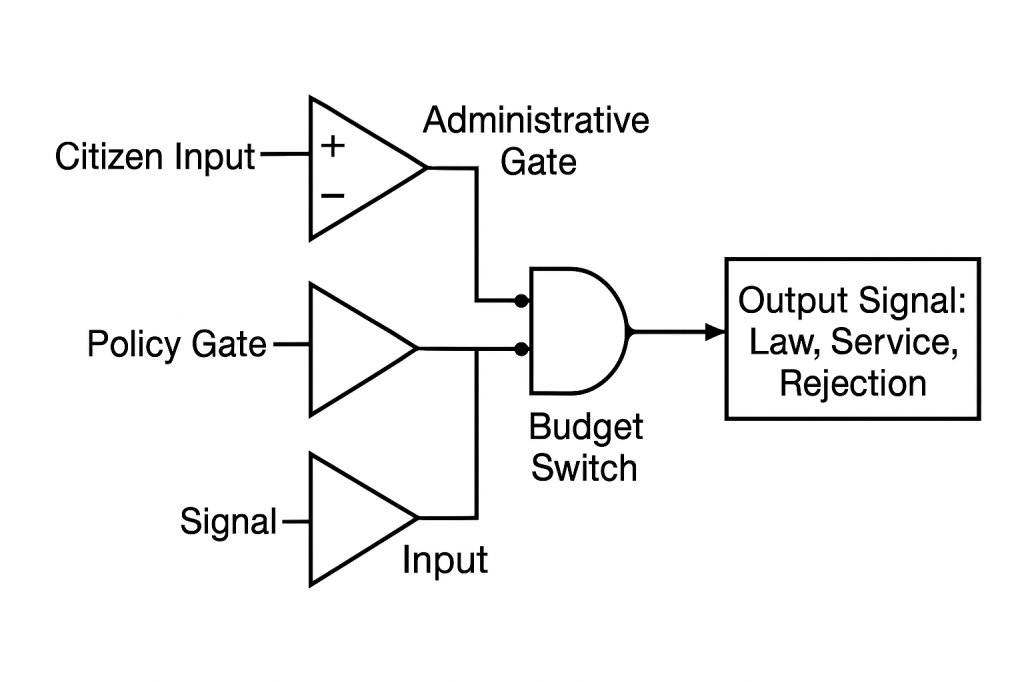
[Citizen Input] → [Administrative Gate]
     ↓                  ↓
[Policy Gate] → [Budget Switch] → [Output Signal: Law, Service, Rejection]
Explanation:
This schematic models how government processes requests and behaviors through layered logic:
- Citizen Input (Op-Amp Buffer)
- The buffer amplifies or conditions raw demands (needs, proposals, violations).
- Provides isolation so downstream logic isn’t driven directly by noisy inputs.
- Administrative Gate (Comparator/Buffer)
- First decision node checking formal compliance (paperwork, basic eligibility).
- Passes approved signals onward; rejects or holds back everything else.
- Policy Gate (Buffer)
- Applies higher-level rules and regulations (statutes, policy frameworks).
- Further filters or redirects requests based on jurisdictional criteria.
- Budget Switch (Logic Gate)
- Combines outputs of Administrative and Policy layers (AND logic):
- Both administrative approval and policy compliance must be true to proceed.
- Routes funds or resources only when both conditions are satisfied.
- Combines outputs of Administrative and Policy layers (AND logic):
- Output Signal
- Law (new regulation enacted)
- Service (public program delivered)
- Rejection (denial or fine)
Key Points:
- Series & Parallel Layers: Administrative and Policy gates operate in series before joining at the Budget switch.
- Constraints, Delays, Buffers: Each gate adds processing time, resource limits, and queuing (buffers) to handle volume.
- Feedback & Revision: Real systems loop rejected or modified signals back for amendment (not shown here).
Each layer adds logic. And every node has constraints, delays, and buffers.
2. Constitution = Persistent Logic Memory (Firmware ROM)
A constitution is not flexible code, it’s read-only logic:
- Interpreted by courts
- Compared to incoming laws
- Used to block invalid signals
Diagram: Constitutional Comparator
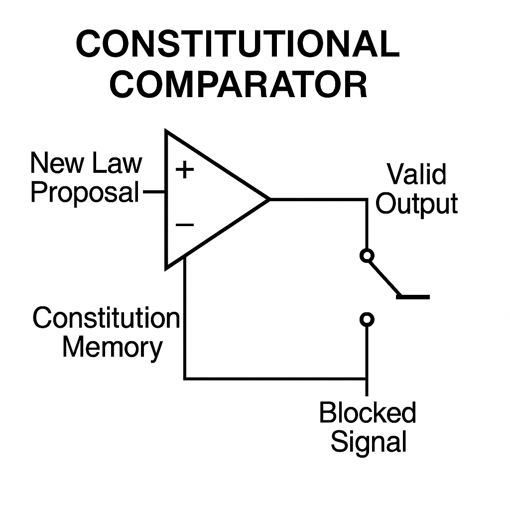
[New Law Proposal] → [Comparator] ← [Constitution Memory]
                ↓
         [Valid Output] / [Blocked Signal]
Explanation:
- New Law Proposal (+): Input signal to comparator.
- Constitution Memory (–): Read-only ROM providing fixed reference logic.
- Comparator: Evaluates proposal against constitutional rules.
- Switch: Routes output:
- Valid Output when comparator output ≥ reference.
- Blocked Signal when output < reference.
This circuit enforces immutable, foundational logic: invalid laws are blocked at the hardware level.
This is foundational logic, the core ROM of the collective system.
3. Law = Circuit Path Regulator
Laws don’t just restrict, they shape signal flow:
- They gate behavior
- Encode feedback conditions
- Apply punishment signals
Diagram: Law as Control Gate
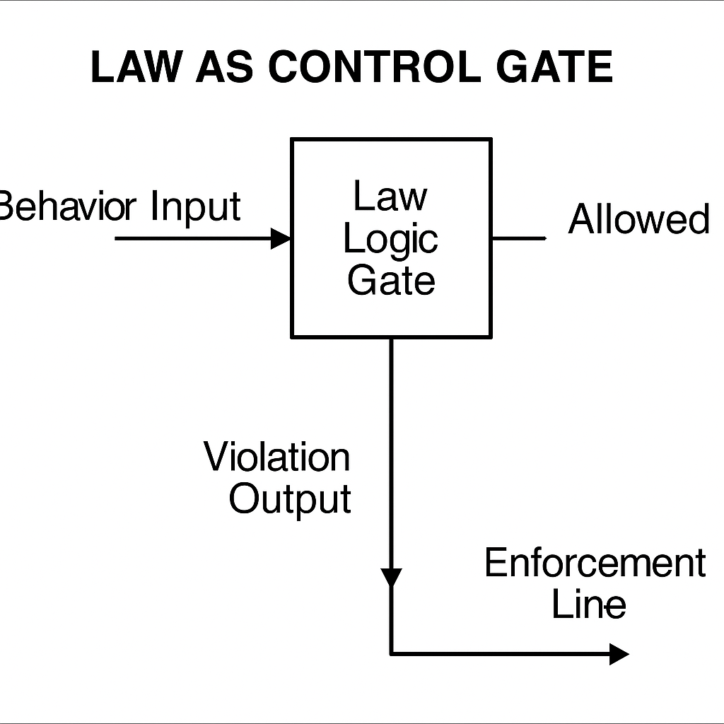
[Behavior Input] → [Law Logic Gate]
         ↓
     [Allowed] / [Violation Output → Enforcement Line]
Explanation:
- Behavior Input: The action or signal entering the legal gate.
- Law Logic Gate: Applies statutory rules, feedback, and penalty conditions.
- Allowed: Output path when behavior complies with laws.
- Violation Output → Enforcement Line: Route for noncompliant behavior triggering enforcement signals.
Transparent, scalable, fair logic prevents error states by gating and routing flows correctly.
4. Regulatory Bodies = Dynamic Signal Buffers
Agencies (like EPA, IRS, etc.) are buffer circuits:
- Adjust signal levels (market, environment)
- Delay harmful feedback
- Absorb or discharge excess pressure
Diagram: Regulator Subcircuit
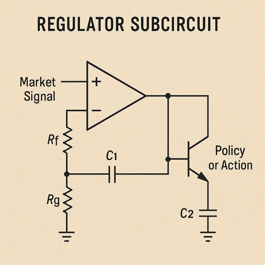
[Wild Market or Crisis Signal] → [Buffer Logic Unit]
                    ↓
          [Output Stabilized → Policy or Action]
Explanation:
- Market Signal → Buffer Logic Unit (Op-Amp + Rf/Rg):
- The op-amp and resistor network sense wild market or crisis signals.
- Rf/Rg set gain, adjusting the signal level before further processing.
- Delay & Absorption (C₁):
- The series capacitor C₁ slows rapid swings, buffering sudden shocks.
- Acts like an agency holding action until conditions stabilize.
- Stabilized Output → Policy or Action (Transistor + C₂):
- The transistor stage sources policy or enforcement signals based on the buffered voltage.
- C₂ at the emitter smooths and discharges excess “pressure,” preventing spurious enforcement bursts.
- Dynamic Signal Buffer Role:
- Adjusts raw inputs to safe operating levels.
- Delays harmful feedback until it can be managed.
- Absorbs/Discharges excess to protect the system from overload.
- Thermal Runaway Risk:
- Remove or weaken any buffering element (gain control, delay cap, discharge path) → uncontrolled oscillations → system collapse.
When regulators are removed or weakened? The system goes into thermal runaway.
5. Amendment, Reform, Revolution = System Rewrite
Sometimes logic must evolve:
- Amendments modify firmware via special override gates
- Reform re-routes existing pathways
- Revolution replaces the board
Diagram: System Update Pathways
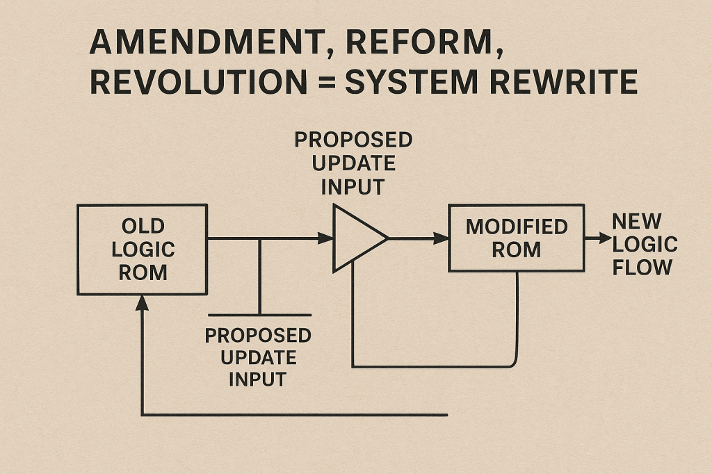
[Old Logic ROM]
     ↓
→ [Proposed Update] → [Threshold Gate: Consensus]
     ↓
→ [Modified ROM] → New Logic Flow
Explanation:
- Old Logic ROM: The existing, unchanging firmware that defines current system rules.
- Proposed Update Input: The amendment or reform data stream, new code, policy tweaks, or revolutionary designs.
- Threshold Gate (Consensus): A special override gate that compares “Old ROM” output and “Proposed Update.”
- Below threshold → gate passes Old Logic unchanged (no amendment).
- Above threshold → gate switches to Proposed Update (amendment via override).
- Modified ROM: The new firmware image written when the gate opens, contains updated logic.
- Feedback Loop (Revolution): Modified ROM output is routed back into the Old Logic ROM block, fully replacing the core firmware when wholesale rewriting is required.
- New Logic Flow: The updated behavior path the system now follows.
Together, this circuit lets you:
- Amend via the override gate when consensus is met.
- Reform by routing updates into existing pathways.
- Revolutionize by looping the new image back to replace the old ROM, preventing stale logic from fossilizing behavior.
This prevents stale logic from fossilizing behavior.
Applications
- Visualize law as logic flowcharts for education
- Diagnose bureaucratic dysfunction as misrouted circuits
- Build games/sims where legal logic is tweakable in real-time
- Help communities debug local governance through feedback diagnostics
- Design policy systems with transparent, editable laws
Insight
Law is circuitry.
Governance is signal regulation.
Freedom isn’t the absence of gates, it’s a well-designed flow architecture.
When we see governments as logic systems, we stop arguing ideology, and start fixing the actual wiring.
Part 21: Ideology as Circuit Logic – Dogma, Belief Cascades, and Narrative Encoders
“Ideology is not opinion, it’s circuitry. It’s belief wired into logic gates, reinforced by feedback loops, and protected by contradiction filters. Dogma is just a signal that can’t be interrupted.”
As we’ve seen, emotions, institutions, and markets all follow system logic. But now, we enter the most subjective-seeming domain and reveal its machinery: belief systems.
Ideology isn’t abstract, it’s a self-sustaining circuit:
- Accepts selective inputs
- Rejects contradictions
- Routes all signals through internal logic
- Modifies behavior outputs across a network
It is a belief engine with rules, defenses, and replication systems. Let’s draw it.
1. Ideology = Recursive Logic System
At its core, ideology is a set of AND, OR, NOT gates wired to produce fixed outputs from preferred inputs.
Diagram: Ideological Logic Board

[Experience] → [Belief Gate: "This Means That"]
     ↓
→ [Logic Filter: Consistency with Doctrine?]
     ↓
→ [Action Output: Behavior / Vote / Judgment]
Explanation:
- Experience → Belief Gate (“This Means That”)
- Incoming events feed into a dedicated “belief” block (an AND/OR structure) that maps raw experience onto predefined interpretations (“this outcome implies that principle”).
- Belief Output → Logic Filter (Consistency Check)
- The interpreted signal then passes through a filter gate that enforces doctrinal consistency.
- Only signals that satisfy the ideology’s core rules (all required conditions met, forbidden combinations blocked) are allowed through.
- Filtered Signal → Action Output
- The approved signal drives the Action Output block, which issues the actual behavior or decision (vote, judgment, speech).
- Action Output → Behavior/Vote/Judgment
- The final output is the observable action or choice, closed‐loop back into the system as new “experience.”
- Recursive Feedback Loop
- The action’s consequences feed back into Experience, reinforcing the same belief-interpretation cycle.
- More loops (layers of gates) make the system increasingly rigid, every new input is forced through the same fixed logic, resisting change.
In this way, an ideology functions like a self-contained logic board: discrete gates enforce “what counts” as valid input, filter for doctrine, and produce predictable outputs, all while recirculating results to sustain the system.
The more recursive the belief system, the harder it is to alter its circuit layout.
2. Dogma = Locked Logic Gate + Feedback Clamp
Dogma is belief that’s resistant to update:
- Incoming contradictory signals are blocked
- Feedback only reinforces existing state
Diagram: Dogma Lock

[Contradictory Evidence] → [NOT Gate + Clamp] → BLOCKED
         ↓
↺ Reinforcement Feedback to Core Belief
Explanation:
- Contradictory Evidence (– input): Feeds into the inverting (–) input of the op-amp, representing challenges to belief.
- Core Belief Ref (+ input): The non-inverting (+) input is held by R from the feedback node, setting the reference level for the belief.
- Op-Amp (Comparator): Outputs high whenever evidence deviates (negative input drop below reference), acting like a NOT gate for contradictions.
- Clamp Diode (D): Oriented from blocked node to feedback node, it allows current only when output is high, preventing the blocked node from discharging back into feedback when output is low.
- Blocked Node: Directly at the op-amp output junction; represents where contradictory signals are trapped.
- Reinforcement Feedback Loop: The blocked node voltage passes through R via the diode to the feedback node, then loops back to the + input, reinforcing the core belief each cycle.
- Closed-Loop Dogma: Any contradictory input is inverted (op-amp), blocked (diode clamp), and fed back (resistor) to the core reference, locking the belief state and resisting change.
It is a closed loop, where deviation is automatically interpreted as threat.
3. Belief Cascades (Echo Chamber) = Signal Amplification Across Nodes
Beliefs spread through social logic:
- One node accepts signal
- Others receive, compare, and copy
- System-wide belief forms
Diagram: Belief Cascade

[Initial Signal] → [Node A Belief Logic]
                   ↓
          → [Node B: Confirmation Loop]
                   ↓
          → [Node C...N] → Feedback Amplifies Belief
Explanation:
This schematic models how an idea propagates and intensifies through a network of validating “nodes,” producing a self-reinforcing consensus:
- Initial Signal → Node A (Belief Logic A)
- The raw message enters Node A’s comparator (an op-amp stage).
- If the signal exceeds Node A’s acceptance threshold, it outputs a “believed” version.
- Node A Output → Node B (Confirmation Loop B)
- Node B takes Node A’s output into its inverting (–) input and the same initial signal into its non-inverting (+) input.
- When both match (confirmation), Node B amplifies the belief and feeds it back into the initial source, reinforcing Node A’s input.
- Node B → Nodes C…N (Cascade Nodes)
- Each subsequent buffer or amplifier (C through N) simply repeats and slightly boosts the confirmed signal.
- These act like followers copying the approved version, ready to pass it on.
- Cascade Amplification & Feedback
- The output of Node N is routed back as a large-scale feedback into the top of the chain (into Node A’s comparator).
- This feedback raises the acceptance threshold and gain in Node A (and B), making the network ever more sensitive to the same signal and less tolerant of deviations.
- System-Wide Consensus (Echo Chamber)
- Through these layered amplifications and feedback loops, even a small initial signal becomes a dominant, self-sustaining belief across all nodes.
- Contradictory signals are drowned out or rejected at each comparator, ensuring the cascade remains locked in, creating an echo chamber rather than open inquiry.
This creates ideological consensus, or echo chambers.
4. Narratives = Logic Encoders for Emotion + Identity
Narratives are encoded belief logic:
- Abstract beliefs embedded in story
- Emotion used as signal amplifier
- Identity fused with moral logic
Diagram: Narrative Encoder

[Story Input] → [Moral Logic Filter] → [Emotional Amplifier]
      ↓
→ [Belief Module Update] → [Behavior Output Aligned with Story]
Explanation:
This schematic shows how narratives wire together abstract ideas, emotions, and identity to rewrite belief systems:
- Story Input → Moral Logic Filter (Logic Encoder)
- The incoming narrative is first processed by a “logic encoder” stage (modeled here as a buffer or comparator).
- This stage extracts the core moral or ideological rules embedded in the story (“good vs. evil,” “us vs. them,” etc.).
- Logic Filter Output → Emotional Amplifier
- The distilled moral signal then drives an emotional amplifier block.
- Emotions (fear, pride, outrage) act like gain in an amplifier, small narrative cues become large affective signals.
- Emotional Amplifier → Belief Module Update
- The amplified emotional output feeds into the belief‐storage module.
- Here, new or strengthened beliefs are written into the “firmware” of identity, what you feel becomes what you believe.
- Feedback Loop → Moral Logic Filter
- Belief updates loop back to bias the initial logic filter, making you more receptive to narratives that fit your reinforced identity and less receptive to those that don’t.
- Behavior Output Aligned with Story
- Finally, the updated belief module drives observable behavior (speech, actions, voting), perfectly aligned with the original narrative.
In essence, stories aren’t just entertainment, they’re logic circuits that encode moral rules, amplify them with emotion, write them into your identity, and then feed back to lock in ever stronger conviction.
The most powerful beliefs are felt, not reasoned.
5. Extremism = High-Gain Ideology Without Damping
Extremist systems amplify belief logic without resistance:
- Every event is interpreted through ideology
- Contradiction raises signal instead of attenuating it
Diagram: Unclamped Belief Loop

[Trigger Event] → [Belief Gate]
           ↓
→ [Amplifier] → [Feedback Without Clamp] → Escalation
Explanation:
- Trigger Event: Voltage source on the left represents the initiating input signal.
- Belief Gate (Op-Amp 1):
- Non-inverting (+) receives the Trigger Event directly.
- Inverting (–) tied to a weighted sum node.
- Rg pulls the sum node toward ground; Rf injects Amplifier output back into this node, combining Trigger and feedback.
- Amplifier (Op-Amp 2): Non-inverting amplifier boosts the Belief Gate output.
- + input connected to Belief Gate output.
- – input fed from output via resistor network inside its box (high gain).
- Escalation Output: Amplifier’s output node is the “Escalation” signal.
- Feedback Without Clamp: The Escalation node loops back through Rf into the Belief Gate’s inverting summing junction, with no clamp or diode to limit gain.
Because there’s no clamping element, every pass through the loop multiplies the signal further, causing runaway belief amplification characteristic of extremist logic.
Extremism is not “radical ideas”, it’s malfunctioning belief logic.
Applications
- Diagnose ideological rigidity in teams, movements, or systems
- Visualize belief systems as modifiable logic boards
- Model persuasion, propaganda, or deradicalization through schematic re-routing
- Design education systems that teach how to trace beliefs, not just accept or reject them
- Build cognitive maps for therapy, ethics, and civic engagement
Insight
Ideology is not just belief, it’s circuit logic wired into the brain, reinforced by group behavior and memory encoding.
To change it, don’t shout. Trace the signal. Identify the gates. Apply a different input at the right voltage, with timing, feedback, and respect.
That’s not manipulation. It’s reengineering belief.
Part 22: Designing People – How to Build Personalities, Characters, and Agents from Circuits
“A person is not a blank slate. They’re like a circuit board. Wired with feelings, logic, memory, delays, filters, and loops. Personality is not a mystery, it’s a schematic.”
We’ve explored how emotions, beliefs, institutions, and markets follow logic. Now we use that knowledge creatively: to design people, not just in theory, but as working circuits.
This has applications in:
- Writing characters for stories and games
- Modeling psychological traits for simulations
- Creating personalized learning and coaching systems
Let’s build a human.
1. Personality = Default Circuit Configuration
Each person has a default wiring:
- Capacitor size (emotional depth)
- Feedback loop types (rumination vs reflection)
- Gate thresholds (impulsivity vs caution)
- Memory recall speed (trauma echo vs mindfulness)
Diagram: Basic Personality Template

[Input: Life Signal] → [Filter: Belief Gates]
         ↓
→ [Capacitor: Emotional Storage] → [Behavior Logic Gates]
         ↓
↺ [Feedback Loop: Learning or Reinforcement]
Explanation:
- Life Signal → Filter/Belief Gates (Op-Amp):
- + input: Raw experience.
- – input: Feedback from resistor R node, setting impulsivity vs caution thresholds.
- Emotional Storage (Cf):
- Cf capacitor from filter output to summing junction feeds the Behavior Logic and feedback path.
- Value of Cf controls emotional depth, larger for trauma echo, smaller for quick mindfulness.
- Behavior Logic Gates:
- A standard logic gate block receives both filter output and stored emotional charge.
- Processes these signals to decide behavior patterns.
- Feedback Loop (Learning/Reinforcement):
- Behavior Out node connects through diode D into resistor R to the summing junction at the filter’s – input.
- R value tunes rumination (low R) vs reflection (high R).
- Diode D ensures one-way reinforcement of certain behaviors.
- Personality Variation:
- Each component’s value (Cf, R, gate thresholds) varies per individual, creating a unique but consistent personality circuit.
No two boards are identical, but they follow consistent logic.
2. Characters = Archetypal Logic Boards
You can design archetypes as specific circuit motifs:
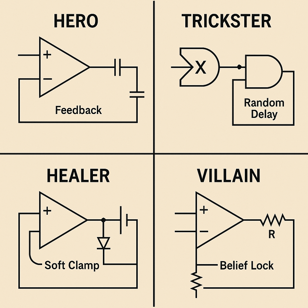
| Archetype | Key Circuit Traits |
|---|---|
| Hero | High output gate, feedback resilience, delayed capacitor discharge |
| Trickster | Signal inverter, XOR gate logic, unpredictable feedback delay |
| Healer | High-capacity buffers, soft clamps, empathy transducers |
| Villain | High-gain amplifier, no contradiction path, belief lock |
Explanation:
- Hero (top-left):
- Standard non-inverting op-amp.
- Output drives a series capacitor and a large reservoir capacitor to ground.
- Strong feedback loop (“Feedback Resilience”) delays discharge.
- Trickster (top-right):
- XOR gate inverts or passes signal based on toggle.
- Output feeds an AND gate.
- AND gate output loops through a random delay element (“Unpredictable Feedback Delay”).
- Healer (bottom-left):
- Unity-gain buffer (op-amp follower).
- Soft clamp via diode to ground (gentle discharge).
- High-capacity reservoir capacitor at output.
- Feedback loop modulates soft clamp (“Empathy Transducer”).
- Villain (bottom-right):
- High-gain non-inverting amplifier.
- Direct resistor network to set high gain.
- No feedback clamp path (“Belief Lock”), preventing contradiction discharge.
These aren’t stereotypes. They’re signal blueprints.
3. Design Modules for Behavior
Modular circuits let you mix traits:
- Add a fear filter (resistor to new signals)
- Insert a trust delay (capacitor + diode)
- Set a forgiveness reset latch
Diagram: Modular Design Example
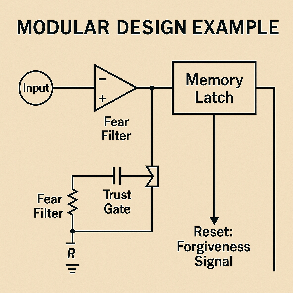
[Input] → [Fear Filter] → [Trust Gate] → [Memory Latch]
                                 ↓
                        [Reset: Forgiveness Signal]
Explanation:
- Fear Filter:
- Op-amp (Belief Gate): Comparator with input from “Input” and feedback threshold.
- Resistor R: From summing node to ground, attenuating incoming signals to model fear sensitivity.
- Trust Gate:
- Capacitor (C): Series to ground with R forms a delay element.
- Diode (D): Allows only forward charges to pass, modeling trust build-up.
- Memory Latch:
- A standard digital latch block capturing the delayed, gated signal.
- Holds the state until reset.
- Reset: Forgiveness Signal:
- Direct line into the latch’s reset input.
- Clears stored state when activated, modeling forgiveness.
This configuration shows modular trait insertion demonstrating emergent behavior through module interaction.
Behavior is emergent from module interaction.
4. Life Events

Explanation:
- Life Events: Input box driving the Belief Gate.
- Belief Gate (Op-Amp): Compares Life Events with feedback, sets belief signal.
- Decision Pacing (Timer RC Delay): RC network slows the belief signal to pace decisions.
- Memory/Emotion Storage (Capacitor): Symbol inside the timer box stores charge for memory/emotion depth.
- Feedback Adjuster (Rf): Logic gate symbol within a box denotes a tunable resistor controlling learning rate.
- Contradiction Gate (NOT + Diode): Triangle inverter with a diode clamp in a box blocking conflicting signals.
- Behavior Output: Final block labeled OUT, loops back to the Belief Gate input for adaptive learning.
5. Identity = Feedback Summary + Memory Architecture
Identity isn’t fixed, it’s the net state of circuits:
- Beliefs + Emotion Memory + Loop History
- Output states reinforced over time
- Reset possible, but requires voltage + logic update
Diagram: Identity Evolution

[Life Input] → [Circuit Board]
           ↓
→ [Current Output] ↺ [Feedback Loop] → Identity Drift or Reinforcement
Explanation:
- Life Input → Circuit Board:
The “Life Input” box represents all incoming experiences. A direct arrow also leads from it to the “Reset” line, indicating that major inputs can prompt a reset. - Circuit Board:
Contains a capacitor symbol beneath it, modeling “Emotion Memory” storage. - Circuit Board → Amplifier → Current Output:
The board’s processed state feeds an amplifier (triangle) whose output is the “Current Output.” - Feedback Loop:
From the amplifier output, a line loops back to the right side of the Circuit Board, indicating reinforcement or drift over time. - Reset Path:
At the bottom, the output line also forms a path labeled “Reset” that returns to the board, requiring sufficient “voltage” and logical trigger to reinitialize memory.
People change, when their circuitry is restructured.
Applications
- Writers: Build deep, believable characters as logic systems
- Therapists: Map client behavior schematically
- Game designers: Simulate dynamic NPCs with real emotional loops
- Educators: Tailor learning to personality circuits
Insight
People are not algorithms, they are circuits with feeling.
Every trauma is a capacitor. Every choice, a gate. Every change, a feedback rewrite.
You don’t have to guess what someone is like. You can draw them, not to limit, but to understand. And from understanding, comes empathy.
Part 23: Debugging Society – How to Diagram a System’s Failure and Rewire It
“When a system fails, it’s not random. It’s a short, a misroute, a gate stuck open, a feedback loop gone critical. Societies don’t need to be saved, they need to be debugged.”
By now, you’ve seen how emotional circuits shape individuals, how logic gates define relationships, and how feedback loops structure economies and governance. But what happens when the system as a whole stops working?
Social failure isn’t a black swan. It’s a signal pattern. We can trace it, diagram it, and most importantly, redesign it.
1. System Failure = Mismatch Between Input and Output
When systems fail:
- Signals go in (needs, protests, innovation)
- But outputs are incorrect (neglect, suppression, inefficiency)
This means the logic gates are broken, or the path is blocked.
Diagram: Failure Path
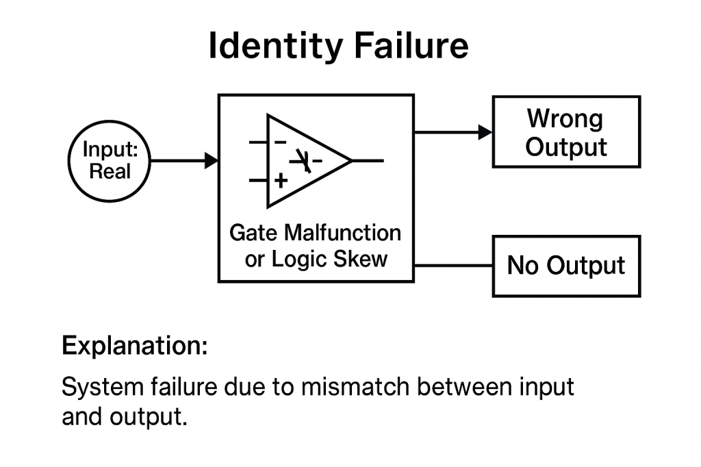
[Input: Real World Need] → [Gate Malfunction or Logic Skew]
                ↓
         → [Wrong Output] or [No Output]
Explanation:
- Input: Real World Need: The circle on the left represents actual demands or issues.
- Gate Malfunction or Logic Skew: The central block contains a broken comparator symbol, indicating faulty logic.
- Wrong Output: The top path shows an output box labeled “Wrong Output,” where the system produces incorrect results.
- No Output: The bottom path leads to “No Output,” representing suppression or failure to respond.
- Overall Failure: This mismatch between input and output signifies system stress from distorted signals, caused by broken gates or blocked pathways.
Most societal stress comes from this signal distortion.
2. Feedback Loop Hijacks = Instability or Entrapment
Some systems feed their own failure:
- Bad policy → Worse outcome → More bad policy
- Inequality → Less opportunity → More inequality
These are positive feedback loops without clamps.
Diagram: Entrenched Feedback
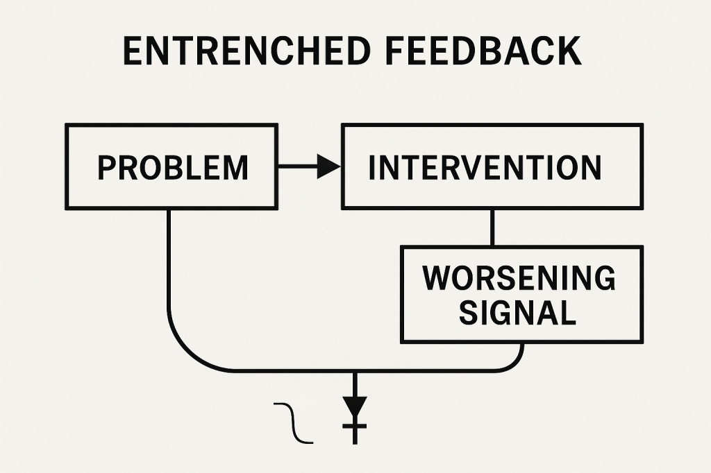
[Problem] → [Intervention] → [Worsening Signal]
                      ↓
               ↺ Feeds Back to Start
Explanation:
- Problem → Intervention → Worsening Signal:
− The box labeled Problem is the start of the loop.
− An arrow leads to Intervention, representing policy or action.
− Downward from Intervention is Worsening Signal, showing that the intervention backfires. - Positive Feedback Loop:
− From Worsening Signal, a curved line returns to Problem, indicating that the failing outcome feeds back into the original issue.
− No clamp or resistance is shown, representing an unchecked, runaway cycle. - Loop Consequence:
− This entrenched feedback amplifies failures—each cycle worsens the problem.
− Breaking the loop requires inserting delays (RC networks), new logic gates, or clamps (diodes/resistors) to prevent direct reinforcement.
To break it: insert delay, new logic, or output clamps.
3. Contradiction Gridlock = XOR Loop With No Resolution
Systems freeze when multiple inputs:
- Conflict without resolution logic
- Compromise paths blocked
- Feedback ignored
Diagram: Contradiction Lock
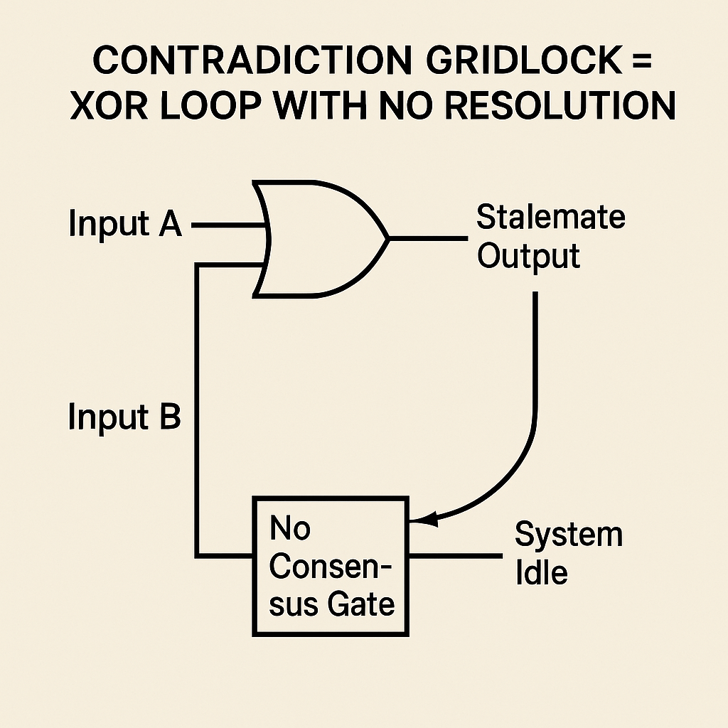
[Input A] XOR [Input B] → [Stalemate Output]
         ↓              ↖
    No Consensus Gate → System Idle
Explanation:
- Input A XOR Input B: The two inputs feed an XOR gate. When they differ, the gate outputs “Stalemate” (true), but when they agree, there’s no decisive signal (false).
- Stalemate Output → No Consensus Gate: The “Stalemate” signal loops into a downstream “No Consensus” block, there’s no path for compromise or synthesis.
- No Consensus Gate → System Idle: Since the gate never resolves the conflict, its output is an idle or blocked state, nothing progresses.
- Feedback Loop Ignored: Neither input is adjusted nor is there any damping or alternate logic path, so the system remains stuck in deadlock.
This circuit captures how, in political or cultural gridlock, conflicting inputs without a resolution mechanism produce perpetual stalemate.
This shows up in politics, institutions, and culture wars.
4. Signal Overload = Collapse from Saturation
Too much input:
- Breaks limited channels
- Floods memory systems
- Drowns out processing units
This causes burnout, not just in people, but in whole societies.
Diagram: Overload Path
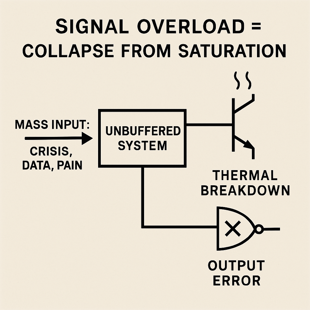
[Mass Input: Crisis, Data, Pain] → [Unbuffered System]
                        ↓
          → [Thermal Breakdown or Output Error]
Explanation:
- Mass Input → Unbuffered System:
A sudden flood of “crisis, data, pain” drives into a system with no buffering or rate-limiting. - Thermal Breakdown (Transistor Symbol):
The unbuffered system’s output overloads its channels, like a transistor driven into thermal runaway, leading to collapse or “burnout.” - Output Error (XOR-with-bubble Gate):
Simultaneously, the overwhelmed system produces garbled or no output, represented by an error gate. - Root Cause:
Without capacitors, resistors, or other buffer/delay elements, input spikes directly saturate processing nodes, flooding memory and logic. - Solution:
Introduce buffering (capacitors, queues), routing (multiplexers), and prioritization logic (filters, gates) to throttle and sequence inputs, preventing system-wide burnout.
Fix it by buffering, routing, and prioritizing logic.
5. Redesign = New Gates, Reset Paths, and Feedback Filters
To debug a society:
- Identify broken gates (where signals stop or misfire)
- Add or reprogram logic (new laws, values, institutions)
- Create reset paths (truth commissions, forgiveness circuits)
- Design feedback filters (media, education, democratic loops)
Diagram: Redesign Schematic

[Current System] → [Diagnostic Layer]
        ↓
 → [Modular Rewire: Logic Gates + Feedback Loops + Reset Buttons]
        ↓
 → [Rebooted Output: Functional, Responsive, Stable]
Explanation:
- Current System → Diagnostic Layer
- The top box represents the existing society or system.
- An arrow leads into a “Diagnostic Layer” where faults are detected (broken gates, misrouted signals).
- Diagnostic Layer → Modular Rewire
- Diagnostics feed into a “Modular Rewire” stage (enclosed box).
- Inside this stage:
- Logic Gates icon: new or reprogrammed rules and institutions.
- Feedback Loop icon (circular arrow): redesigned information channels (media, education, voting).
- Reset Button icon: formal reset paths (truth commissions, forgiveness mechanisms).
- Modular Rewire → Rebooted Output
- The modified signals exit as “Rebooted Output,” characterized by being functional, responsive, and stable.
- This final box signifies a healthier, adaptive society after inserting new logic, feedback filters, and reset paths.
Key Takeaway:
By diagnosing failures, swapping in better logic gates, installing feedback filters, and providing reset mechanisms, even deeply flawed systems can be reconfigured and rebooted toward stability and responsiveness.
No system is perfect. But every system is editable, with the right tools.
Applications
- Diagnose urban inequality as signal blockage
- Map political gridlock as XOR standoff
- Model police reform as feedback re-routing
- Design better voting systems with multi-node feedback
- Visualize post-conflict recovery as circuit repair and latch reset
Insight
Societies aren’t broken because people are evil.
They break because their logic no longer maps to reality.
And just like engineers, we can trace the signal, test the gates, and build a world that responds to its inputs intelligently, not ideologically.
This isn’t politics. This is schematic empathy.
Part 24: Rewiring Ourselves – A Personal Practice of Emotional Circuit Mapping
“You’re not broken. Your wiring is just out of sync. Your habits are loops, your fears are resistors, your shame is charge with no discharge path. But now you know how to see it. And that means you can change it.”
We’ve used circuits to understand society, systems, and culture. But perhaps the greatest application is personal. You are a board.
Every memory, reaction, pattern, and defense is a circuit component, and now, you can map and rewire them.
This is not therapy. It’s schematic introspection. A new practice of self-understanding and emotional engineering.
Step 1: Identify the Trigger Input
Start with a situation where:
- You react intensely
- You feel stuck
- You repeat a behavior you regret
Write the input signal clearly.
Example:
“When someone interrupts me, I shut down.”
Step 2: Trace the Logic Gates
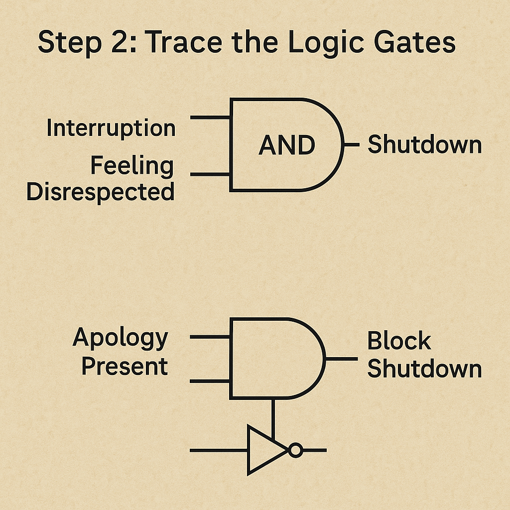
Ask:
- What belief is activated?
- What conditions must be met for the output?
Use AND, OR, NOT logic.
Example Logic:
[Interruption] AND [Feeling Disrespected] → [Shutdown]
Or add suppression:
[Apology Present] → NOT [Shutdown Triggered]
Step 3: Identify Capacitors and Resistors

What are you holding? What slows you down?
- Capacitors = stored memory or trauma
- Resistors = fear, hesitation, avoidance
Example:
[Past Events] → [Capacitor]
    ↓
[New Trigger] → [Low Resistance] → Fast Shutdown
Mapping this helps you locate emotional time-bombs.
Step 4: Map Feedback Loops

Are you reinforcing the pattern?
- Shame → Silence → Isolation → More Shame
- Anger → Reaction → Guilt → Self-criticism → More Anger
Draw the loop.
Diagram:
[Feeling] → [Action] → [Result]
      ↑                 ↓
     ←──── Feedback Loop
Use this to break the loop with new logic or a manual reset.
Step 5: Design the Rewire

Now modify:
- Change thresholds
- Add delay components
- Create reset paths (rituals, reflection, journaling)
- Introduce buffers or comparators
New Circuit:
[Trigger] → [Delay] → [Comparator: Is This About Me?]
                      ↓
         [High Resistance Clamp] → [Balanced Output]
This is personal engineering—and it works.
Real World Practice Tools
- Journal as a signal tracker
- Use flowcharts to map loops
- Write down trigger–logic–response schematics
- Build rituals as resets
- Create visual circuit boards of your emotional patterns
Insight
You are not your reaction.
You are a system, and systems can be restructured.
This is your power.
This is your language.
And this is how we stop running from our circuits, and start becoming their architects.
Part 25: Toolkit, Templates, and Symbol Resources – Fonts, Icons, and Circuit Libraries for Emotional Design
“A new language needs its symbols. A new method needs its tools. The time has come not just to think differently, but to draw differently.”
After exploring emotion, governance, behavior, and economy through circuit logic, you’re ready to build. But like any design system, this requires shared tools: a symbolic vocabulary, template structures, and pre-built logic modules to use and remix.
This post provides you with the practical resources to begin diagramming minds, societies, and selves, visually, logically, and powerfully.
1. Symbolic Circuit Font & Glyph Set
We recommend a standardized visual language inspired by electronics, but adapted for emotional design.
| Component | Symbol | Meaning |
|---|---|---|
| Resistor | ─///─ | Fear, hesitation |
| Capacitor | ─||─ | |
| Diode | ─▶|─ | |
| Comparator | > or < | Belief thresholds |
| NOT Gate | ○ | Inversion, negation |
| AND Gate | ∧ | Requires both inputs |
| OR Gate | ∨ | Requires either input |
| Oscillator | ~~~ | Repetitive pattern (rumination, loop) |
| Latch | ⎍ or ⏣ | Locked memory state |
| Feedback Loop | ↻ or ⮌ | Self-reinforcing signal |
Use these consistently across your diagrams to teach and share more effectively.
2. Template Sheets for Personal and System Design
Available template types:
- Emotional Behavior Sheet: Trigger → Logic → Output map
- Conflict Diagram: Inputs from multiple parties, contradiction gates
- Group Logic Board: Collective signal mesh, feedback conditions
- Institutional Processor: Role-based modular diagrams for organizations
- Economic Flow Map: Wealth and labor as energy transfer
- Self-Rewire Plan: “Current Pattern vs New Path” comparison
You can draw these manually or using circuit diagramming software like Fritzing, Draw.io, or Lucidchart (custom symbol sets recommended).
3. Modular Logic Libraries

Reusable sub-circuits:
- Forgiveness Unit: Latch + Reset + Delay
- Repression Filter: Capacitor + NOT + Oscillator leak
- Procrastination Gate: AND Gate + Delay + Reversed Output
- Grief Path: Emotional capacitor + long resistor chain
- Revolt Pulse: Overload path + alternate feedback circuit
- Hope Circuit: Weak signal + amplifier + feedback comparator
These can be copy-pasted into larger models or used as metaphorical conversation starters.
4. Infographic and Display Options
How to visualize your circuits:
- Posters for classrooms or therapy offices
- Printable character sheets (for RPGs, coaching, or writing)
- Interactive interfaces for apps or mental health tools
- Slide decks for presentations, workshops, or public systems design
When done well, these diagrams invite dialogue, not dogma.
5. Distribution and Collaboration
Your schematic language can be:
- Taught in workshops
- Used in co-design meetings
- Applied in conflict mediation
- Expanded by artists, designers, educators
- Shared in zines, toolkits, or public art
Imagine a symbolic commons, a shared visual grammar for human systems.
Insight
This toolkit is not the end. It’s the beginning of a design revolution, not in machines, but in us.
We can now draw:
- A mood.
- A movement.
- A nation.
- A self.
Let’s make the invisible visible.
Let’s wire clarity where there was confusion.
Let’s build better minds, institutions, and futures, one circuit at a time.
This completes the 25-part series on Signals and Circuit Symbolic Behavior. You now hold the tools, language, logic, and philosophy to begin schematic re-design of everything that matters.


Leave a reply to usually917af79438 Cancel reply